4445104419 / 2024-04-23/ Page 4 of 4
9:
1. In case you have just the control PCB as a spare part proceed with figure 10.
2. In case you have the control PCB assembled to the metal holder as a spare part
release the 3 nuts and exchange the control PCB incl. metal holder.
3. When fitting the new control PCB, follow the above working steps in the reverse
order and fix the cables in the same way.
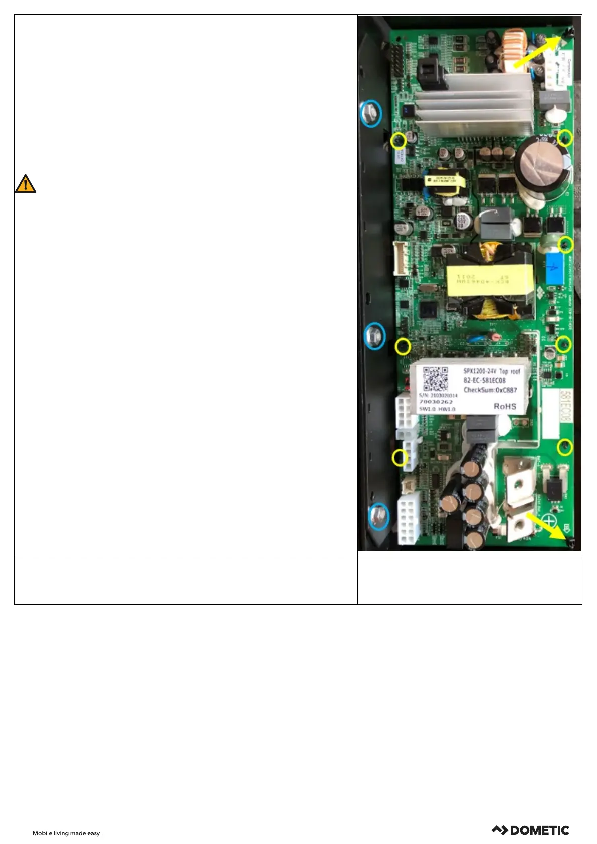
10:
1. Cut the two cable ties that fixes the PCB to the metal holder in the edges.
2. Carefully push the 7 locking device that holds the spacers in place and remove the
PCB.
3. Place the new PCB on the protruding spacers.
4. When fitting the new control PCB, follow the above working steps in the reverse
order and fix the cables in the same way.
CAUTION!
Place the plastic clip with the temperature sensor at the same position at the evaporator
(figure 5 (page 2)).
When fitting the connection cable, tighten the 2 fastening screws at a maximum torque
of 3.5 Nm. Make sure the cables do not touch any components on the control PCB (heat
sink, etc.)
When fitting the new PCB with the metal holder into the unit, position/route the cables
in the same way and fix them at the same points with cable ties.
When fitting the metal holder, tighten the 2 fastening screws at a maximum torque of
4 Nm.
When fitting the suction grill, tighten the fastening screws at a maximum torque of 1 Nm.
Otherwise, they might turn idle.
1. When reassembling the unit make sure that no cables are pinched and all lose parts
(cable tie residues, etc.) are removed from the system.
2. Check the function in a concluding test run.

 Loading...