BOOSTER PUMP SYSTEM 53
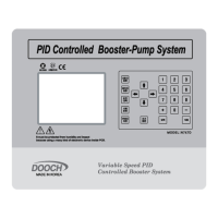
BOOSTER PUMP SYSTEM N747D
LMC Error lamp relay C contact 24: EMST System emergency operation signal terminal
2: LMA Error lamp relay A contact 25: RUN System start/stop signal terminal
3: SFC Sysetm error relay C contact 26: S1NT Pressure sensor1 (-) terminal
4: SFA Sysetm error relay A contact 27: S1PT Pressure sensor1 (+) terminal
5: SRC
Sysetm operation Relay C
28: LV2T Low level sensor 2 input terminal
6: SRA
Sysetm operation Relay A
29: LV1T Low level sensor 1 input terminal
7: S2NT Pressure sensor2 (-) terminal 30: CAN- CAN signal low terminal
8: S2PT Pressure sensor2 (+) terminal 31: CG CAN signal earthing common terminal
9: CG Earthing common terminal 32: CAN+ CAN signal high terminal
10: PSWT
Emergency pressure siwtch
33: CG Earthing common terminal
11: 485- RS485 signal Low terminal 34: VO0 inverter 0 frequeancy setup voltage(0~10V)
12: CG
RS485 signal earthing
common terminal
35: iO0 inverter 0 frequeancy setup current(0~11V)
13: 485+ RS485 signal High terminal 36: CG Earthing common terminal
14: RI0C
Inverter 0 initializing relay C
contact
37: IOFT Inverter 0 error recognition terminal
15: RI0A
Inverter 1 initializing relay A
contact
38: IORT Inverter 1operation recognition terminal
16: PC Mulifunction relay C contact J1 CAN terminating resistence SW(used when short)
17: PA Mulifunction relay A contact J2 RS485 terminating resistence SW(used when short)
18: RI0C
Inverter 0 operation relay C
contact
J3
Inverter 0 frequency setup: current/voltage adjusting SW
19: RI0A
Inverter 1 operation relay A
contact
(
Vout: voltage, lout: current)
20: CG Earthing common terminal
J4
Inverter 1 frequency setup: current/voltage adjusting SW
21: CG Earthing common terminal (Vout: voltage, lout: current)
22: iINT
Externally incoming signal
current(4~20mA)
VR1 LCD display setup
23: VINT
Externally incoming signal
Battery TIME IC backup battery
Main Board