Do you have a question about the dooch Q-Drive NQ-0400-S and is the answer not in the manual?
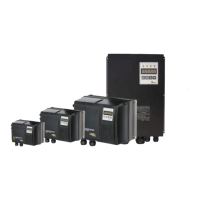
Introduction to the Q-Drive series and the manual.
General guidelines for safe operation and understanding warning symbols.
Details specific warnings and cautions to prevent electric shock, burns, and fire.
Guidelines for safe transport, installation, wiring, and handling of the drive.
Steps for initial operation checks, operational precautions, and error handling.
Recommendations for handling drive failure and ensuring pump system reliability.
Important checks and considerations before starting to use the drive.
Reading nameplate, interpreting model, and basic installation/wiring guidance.
Guidance on proper installation and connecting power/control signals.
Detailed technical specifications of the Q-Drive series products.
Physical dimensions and weight specifications for various Q-Drive models.
Dimension and weight charts for NQ-0400T, NQ-0550T-0750T, NQ-1100T-1500T, NQ-1850T-2200T.
Critical safety and operational considerations for installing the drive.
Visual representation of all terminal connections for main power and control circuits.
Guidelines for correctly wiring the main power supply to the drive.
Precautions and requirements for proper grounding to ensure safety and prevent electric shock.
Recommended wire specifications and terminal screw torque for safe connections.
Procedures for wiring the control circuit for various functions and signals.
Detailed explanation of control terminal block functions and layout.
Connecting sensors and safety guidelines for control circuit wiring.
Wiring for input logic modes and communication lines (CAN/RS485).
Details on the FND display, LED lamps, and button functions for operating the drive.
Step-by-step instructions on how to navigate and change drive parameters.
Visual guide on parameter group/item movement and how to change parameter values.
Details on setting up basic functions for motor and drive operation.
Setup items and their descriptions for common drive configuration.
Parameters for configuring pump control modes and sensor settings.
Setup parameters for controlling the drive via external voltage or current signals.
Parameters required for setting up CAN communication for interoperation.
Setup parameters for optimizing pump system operation and protection.
Parameters for PID control, pump capacity, and lead pump alternation.
Parameters for setting high/low pressure and low water level alarms.
Parameters for storing and deleting fault history logs.
Detailed instructions for single drive operation in constant pressure control mode.
Wiring diagram for single drive operation in constant pressure control mode.
Steps for setting up and operating the drive for constant pressure control.
Table of basic setup parameters for constant pressure control operation.
How to set the target pressure for the pump system, including multi-drive considerations.
How to check and correct the motor's rotation direction for proper pump operation.
Instructions for operating multiple drives together for constant pressure control.
Setup and operation methods for multi-drive systems, focusing on pressure control.
Table of basic setup parameters for multi-drive operation.
Setting target pressure in multi-drive operation, emphasizing CAN communication.
Checking and adjusting motor rotation direction in multi-drive configurations.
Overview of function tables and descriptions for Q Drive parameters.
Explanation of the 'Status Group' display codes (P, S, H, O, U, A, O, I).
Detailed table of parameters for pump control functions, including PID settings.
Table of parameters for drive control, covering motor settings and operation modes.
Setting up and correcting pressure sensors, and configuring PID controller gain.
Setting the integral and derivative gains for the PID controller.
Setting the PID control cycle time and enabling freezing prevention function.
Setting pressure variance for start and time to reduce speed when setup pressure is maintained.
Setting minimum output frequency for stopping and initial output ratio on starting.
Setting the mode for RS485 communication.
Setting ID, speed, and delay time for RS485 communication.
Setting the mode and ID for CAN communication for multi-drive control.
Setting CAN speed and determining drive operation order in multi-drive mode.
Setting the time for lead pump alternation in multi-drive operation.
Setting a delay for the stand-by pump to start operation.
Selecting PID control type for energy efficiency in multi-drive operation.
Setting the standard pressure values for issuing high and low pressure alarms.
Setting the duration for high/low pressure before triggering an alarm.
Setting alarm time and pressure level for low water level detection.
Selecting the method for low water level alarm detection (software or sensor).
List and description of fault codes displayed on the FND.
Options for managing fault history and correcting sensor readings.
Resetting parameters to factory settings and displaying the software version.
Detailed explanations for parameters within the Drive Control Group.
Setting the location for issuing operation commands (FND or terminal block).
Setting target frequency input method and motor capacity/poles.
Setting the rated current and other electrical specifications of the motor.
Setting the motor rotation direction and stopping method.
Setting motor acceleration (rising) and deceleration (falling) times.
Selecting whether to generate a trip upon motor overload.
Setting the trip current level and time against motor overload.
Selecting and setting the stall protection current level.
Setting motor overheat and ground protection functions.
Configuring automatic restart after trip and selecting drive control mode.
Setting torque boost, start frequency, and maximum operation frequency.
Setting switching frequency and cooling fan operation method.
Correcting and displaying consumed power upon drive operation.
Displaying accumulated power and drive temperatures.
Displaying ambient temperature and effective output voltage.
Setting command frequency based on external analog input voltage or current.
Displaying year, month, date, and time set within the drive.
Initialising parameters and providing details for the Drive Control Group.
Table listing FND display codes, content, description, restarting status, and remarks for faults.
Procedures for resetting faults and alarms through the FND and specific groups.
Causes and reactions for specific error codes like Er-01, Er-02, Er-03, etc.
Cause and reaction for low pressure alarm (tLP).
Cause and reaction for low water level alarm (tUL).
Cause and reaction for Arm Short Trip (tASH).
Cause and reaction for H/W Over Current Trip (tOC).
Cause and reaction for H/W Over Current Restriction Trip (SOC).
Cause and reaction for Motor Overheat (tMOH).
Cause and reaction for Overheat Trip (tOH).
Cause and reaction for Low Voltage Trip (tLv).
Cause and reaction for High Voltage Trip (tOv).
Cause and reaction for Motor Overload Operation Trip (tOL).
Cause and reaction for Drive Overload Operation Trip (tdOL).
Cause and reaction for Ground Trip (tGF).
Cause and reaction for Communication ID Duplication (tIdE).
Cause and reaction for Communication Error (tCE).
Cause and reaction for Defects of Input (tIO).
Cause and reaction for Defects of Output (tOO).
Cause and reaction for External Fault Input (tES).
Reaction for Allowable Time Elapsed (tLt).
RS-485 communication specs, protocol, and troubleshooting for connection issues.
Troubleshooting steps when communication between master and drive is not established.
List of parameters with address, scale, unit, R/W status, and contents.
Continuation of parameter list with output power and accumulated power details.
| Brand | dooch |
|---|---|
| Model | Q-Drive NQ-0400-S |
| Category | Controller |
| Language | English |