Do you have a question about the DoorHan BR-PRO6000KIT and is the answer not in the manual?
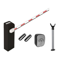
| Type | Automatic Barrier |
|---|---|
| Manufacturer | DoorHan |
| Model | BR-PRO6000KIT |
| Max Barrier Length | 6 m |
| Boom Length | 6 m |
| Barrier length | 6 m |
| Opening angle | 90 ° |
| Power Supply | AC |
| Frequency | 50 Hz |
| Motor Power | 180 W |
| Operating Temperature | -40°C to +55°C |
| Protection Class | IP54 |
| Opening Time | 4-6 s |
| Closing time | 4-6 s |
| Voltage | 230 V |
Specifies the maximum length of the boom arm for different barrier models.
Indicates the time taken for the boom to fully open or close.
Details the required electrical supply voltage and frequency.
Describes the type of boom arm used with the barrier.
Defines the operational duty cycle at a specific temperature.
Specifies the rotational speed of the barrier's motor.
Mentions the temperature limit for motor thermal protection.
Outlines the ambient temperature range for safe operation.
States the power consumption of the barrier unit.
Indicates the degree of protection against solids and liquids (IP rating).
Provides the estimated service life in years or cycles.
Illustrates the correct angular positions for boom adjustment.
Details the control board and programming instructions.