MAINTENANCE 31
9/270, 9/300, 12/235, 17/235, 21/215, 9/270HA, 9/300HA, 10/300HA, 12/235HA, 17/235HA, 21/215HA
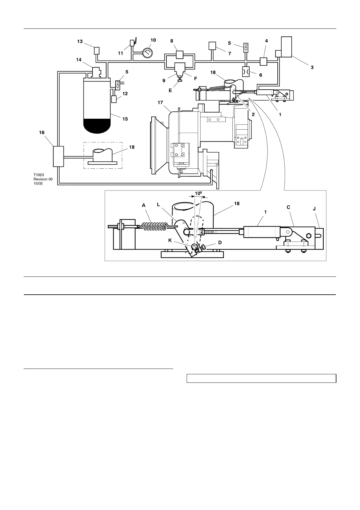
KEY
SPEED AND PRESSURE REGULATION ADJUSTMENT
17/235 21/215
Normally, regulation requires no adjusting, but if correct adjustment
is lost, proceed as follows:
Refer to the diagram above.
With the unit stopped, disconnect ballast spring 'A' from the
butterfly lever. Loosen the two screws securing bracket 'C' to main
bracket 'J'.
Loosen screw 'D' and rotate the butterfly valve pivot shaft 'K' fully
clockwise until the valve is closed. Position lever 'L' approximately 10°
after vertical and tighten screw 'D'.
Keep the butterfly lever in the closed position and with the the air
cylinder fully contracted tighten the screws holding bracket 'C' to the
main bracket 'J'.
Allow the cylinder to return to its extended position and reconnect
the ballast spring 'A'.
Start engine: Note receiver pressure. Warm up pressure should be
3,5-5,0 bar (50-70 p.s.i.).
To increase the warm up pressure, turn the air cylinder rod in an
anti-clockwise direction to open the butterfly valve.
To reduce warm up pressure, turn air cylinder rod in clockwise
direction to close butterfly valve.
When the engine is warmed up, press the service air switch on the
control panel to commence normal regulation.
Set pressure by adjusting the screw 'E' on the pressure regulator
'F'. Turn the screw clockwise to increase pressure and anticlocwise to
reduce pressure.
1 Air cylinder 7 Regulation pressure transducer 13 Pressure transducer
2 Butterfly valve 8 Start/Run solenoid 14 Minimum pressure valve
3 Mini compressor 9 Pressure regulator 15 Separator tank
4 Unloader Solenoid 10 Panel pressure guage 16 Auto blowdown valve
5 Relief valve 11 Manual blowdown valve 17 HR2 Airend
6 Orifice 12 Temperature sensor 18 Air inlet
IMPORTANT: Ensure all components are aligned and move freely.


 To Next Page