EasyManua.ls Logo

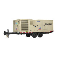
Doosan HP1600WCU User Manual

Doosan HP1600WCU
119 pages
To Next Page IconTo Next Page
Page #1 background imageLoading...
Page #1 background image
HP1300WCU (25/300) B84
COMPRESSOR MODELS
Doosan Infracore Portable Power
1293 Glenway Drive
Statesville, N.C. 28625
DoosanPortablePower.com
Book: 22772784 (12-2012) Rev B
T
D
T
ELECTRONIC SERVICE
HP1600WCU (25/330) B83
MANUAL

Questions and Answers:

Doosan HP1600WCU Specifications

General IconGeneral
ModelHP1600WCU
TypePortable Air Compressor
Maximum Pressure150 psi
Flow Rate1600 cfm
Rated Operating Pressure125 psi
Air Delivery1600 cfm
Drive TypeDirect Drive
Cooling MethodWater-cooled

Summary

Section 1 Manual Description

Manual Content Overview

Describes the manual's organization, scope, and content for service.

Section 2 General Information and Operational Theory

Machine Monitoring and Control System

Details the machine's electronic monitor and control system functions.

WEDGE Controller Operations

Explains the WEDGE controller's role, inputs, outputs, and communication.

Sensors and Transducers

Describes various sensors and transducers used for data collection.

Digital Inputs and Outputs

Explains digital inputs from switches and outputs to control devices.

System Communication and Wiring

Covers controller outputs, engine communication, and data links.

Key Electrical Components

Details the function of essential electrical components like sensors and relays.

Section 3 Operational Information

Control Panel Operations

Covers power ON, engine start-up, and loading sequences of the machine.

Controls, Instruments, and Settings

Describes panel controls, instruments, and display unit configuration.

Wedge Service Diagnostics and ID

Details accessing diagnostics and entering machine identification (ID).

Section 4 Service Tools

Recommended Special Tools

Lists special tools required for performing service procedures.

Section 4 Electronic Systems Troubleshooting Procedures and Techniques

Troubleshooting Fundamentals

Outlines basic steps and approach for effective troubleshooting.

Electrical Measurement Guidelines

Provides guidance on measuring voltage, resistance, frequency, and duty cycle.

Compressor Fault Codes and Flowcharts

Explains compressor fault codes and provides troubleshooting flowcharts.

Section 5 System Schematic Diagrams

System and Panel Wiring Diagrams

Presents overall system wiring and instrument panel schematics.

IQ and CAN Communication Diagrams

Illustrates IQ wiring and CAN communication system schematics.

Section 6 Electronic Component Location Drawings

Electrical Component Locations

Shows the physical placement of key electrical components on the machine.

Section 7 Individual Circuit Diagrams

Engine Start and Fuel Sender Circuits

Details the engine start and fuel level sender circuits.

Temperature and Pressure Sensor Circuits

Explains circuits for temperature and pressure sensors (RT1, RT2, PT1, PT2).

Ancillary System Circuits

Covers DC heaters, startup compressor, filter switches, and coolant sensor circuits.

Section 8 Electrical Connector Information

Connector Parts and Usage

Lists connector parts, their usage, and necessary removal/crimp tools.

Section 9 Electrical Parts List

Electrical Parts List

Provides a comprehensive list of electrical components and their part numbers.

Section 10 Alerts and Shutdowns List

Alerts and Shutdown Conditions

Lists all alert and shutdown codes, their triggers, and indicators.

Engine Fault Code Reference

Details fault codes specific to the QSX15 Cummins engine.

Section 11 Recommended Spare Parts

Recommended Spare Parts List

Lists recommended spare parts for common maintenance and repair.

Section 12 Software Information

Software Updates and Service Manuals

Provides information on obtaining software updates and service manuals.

Related product manuals