Do you have a question about the Doosan NHP1500WCU-T3 and is the answer not in the manual?
Operator and maintenance personnel must understand decals and consult manuals for safe operation.
Safe handling of compressed air, use of PPE, and inspection of pressure equipment.
Substances produced during operation: brake lining dust and engine exhaust fumes.
Precautions for inhalation of fumes and skin/eye contact with lubricants.
Safety guidelines for batteries, radiators, including hot coolant warnings.
Usage and safety precautions for ether starting fluid, avoid ingestion/inhalation.
Guidelines for safe loading, tie-down, and towing of the unit.
Graphic forms and meanings of ISO symbols for prohibition, information, and warnings.
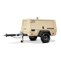
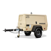
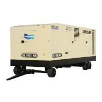
Details on unit models, engine, capacities, dimensions, and weights.
Information on running gear components and a list of expendable service parts.
Identifies and describes the function of each control and instrument on the panel.
Procedures for lifting, securing with wheel chocks, towing, and positioning the unit.
Guidelines for mounting the compressor and connecting remote fuel lines.
Procedure for installing air hose restraining cables to prevent whipping and ensure safety.
Guidelines for parallel operation of multiple compressors, hose sizing, and isolation valves.
Installing signal air lines for automatic pressure modulation and remote pressure selection.
Pre-operation checks including service valves, doors, battery, and fluid levels.
Step-by-step engine starting instructions, including auto-start and ether injection.
Describes loaded/unloaded operation, engine speed control, and monitoring.
Diagram illustrating the controller's logic for start, warm-up, loading, and unloading.
Feature for automatic starting and stopping based on pressure or remote signals.
Procedure for normal and emergency stopping, including cool-down sequence.
Explains controller screens, commands, and menu navigation.
Importance of servicing, schedules, oil checks, and air cleaner maintenance.
Maintenance procedures for gauges, fuel tank, battery, coolers, hoses, filters, fasteners, and drives.
Periodic maintenance tasks and intervals for daily, weekly, monthly, and annual checks.
Specifications for inch and metric fastener torque values.
Importance of lubrication, types of lubricants, and oil change procedures.
Guidance on troubleshooting methodology and initial action steps.
Lists common complaints, potential causes, and corrective actions for operational issues.
Table detailing specific alerts and shutdown conditions with parameters and values.
Core control system, data collection, sensors, and digital I/O functions.
Details controller outputs, loops, engine communication, and electrical systems.
Diagram illustrating the airflow path through the compressor system.
Diagrams showing lubrication, hydraulic, and fuel systems.
Diagrams for heating systems and condensate flow.
| Brand | Doosan |
|---|---|
| Model | NHP1500WCU-T3 |
| Category | Air Compressor |
| Language | English |