MB_4K_Manual_000234_v1_3.doc Page 8 Version 1.3
M4K.OM.000234.DRM Doremi Labs, Inc Confidential
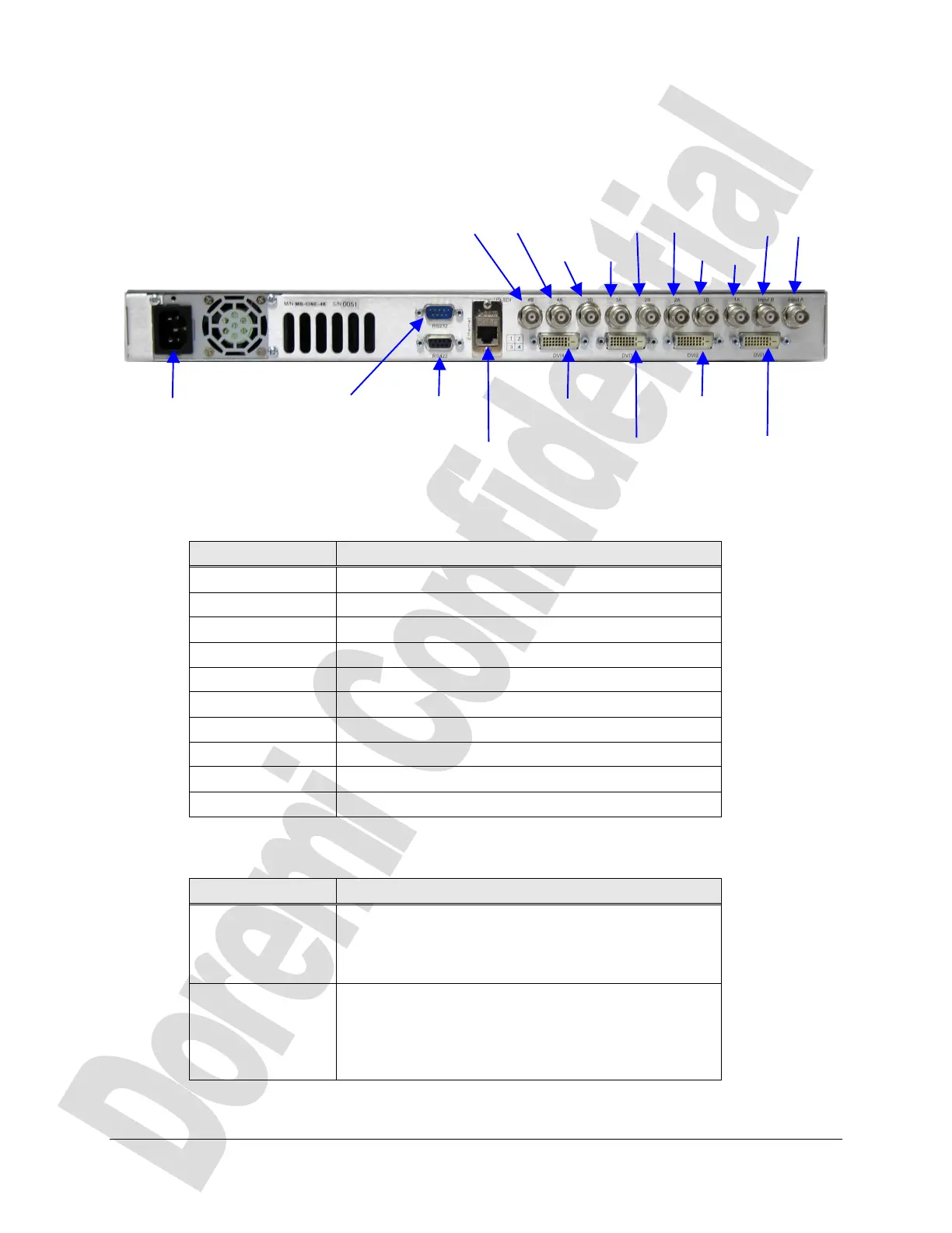
3 Rear Panel Connections
The rear panel allows you how to connect the unit to the power outlet (110VAC / 60 Hz or
220VAC/50Hz).
The following connectors are available:
Figure 2: MB-4K Rear Panel Connectors
The HD-SDI connectors descryption is provided below:
Connector Description
4B HD-SDI output connector : Bottom right, Link B
4A HD-SDI output connector : Bottom right, Link A
3B HD-SDI output connector : Bottom left, Link B
3A HD-SDI output connector : Bottom left, Link A
2B HD-SDI output connector : Top right, Link B
2A HD-SDI output connector : Top right, Link A
1B HD-SDI output connector : Top left, Link B
1A HD-SDI output connector : Top left, Link A
IN-B HD-SDI input connector : Input, Link B
IN-A HD-SDI input connector : Input, Link A
The Serial connectors descryption is provided below:
Connector Description
RS 232 RS232 port to connect to the host. The port settings
are : 38400 bauds, 8 data bits, no parity, 1 stop bit,
no flow control. Use a Null Modem serial cable to
connect from a PC.
RS 422 RS 422 port used for debug messages. The port
settings are : 115200 bauds, 8 data bits, odd parity, 1
stop bit, no flow control. Use a RS232 to RS422
serial cable (also called at Doremi V1 to PC cable,
provided with the unit) to connect from a PC.
Power connector RS 422
debug port
Ethernet
DVI 4 Out
RS 232
Serial Port
DVI 3 Out
DVI 2 Out
DVI 1 Out
4B 4A
3B 3A
2B 2A
1B 1A
IN-B IN-A