This document is an Installation, Maintenance, and Parts Manual for Dorner Variable Speed VFD (Variable Frequency Drive) Controllers, identified by the part number 851-953 Rev. A. These controllers are designed for use with AC motor speed control in both standard and heavy-load VFD gearmotors on Dorner conveyors.
Function Description
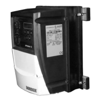
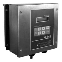
The Dorner Variable Speed VFD Controllers regulate the speed of AC motors used in various conveyor systems. They provide precise control over motor operation, allowing for adjustments in conveyor speed to suit different application requirements. The controllers feature a user-friendly interface with dedicated buttons for increasing and decreasing speed, a display for monitoring settings, and start/stop/enter buttons for operational control.
The manual categorizes controllers into "Industrial Controllers" and "Sanitary Controllers," each with specific model numbers and corresponding electrical specifications.
Important Technical Specifications
The VFD controllers are available in various configurations, supporting different input voltages, phases, and output capabilities.
Industrial Controllers (Examples):
- 32MVA1122(X): 115 Volts, Single Phase input; 230 Volts, Three Phase output; 0.5 HP (0.37 kW); 2.3 Amps max output.
- 32MVA2122(X): 230 Volts, Single Phase input; 230 Volts, Three Phase output; 0.5 HP (0.37 kW); 2.3 Amps max output.
- 32MVA2322(X): 230 Volts, Three Phase input; 230 Volts, Three Phase output; 0.5 HP (0.37 kW); 2.3 Amps max output.
- 32MVA4342(X): 460 Volts, Three Phase input; 460 Volts, Three Phase output; 0.5 HP (0.37 kW); 1.2 Amps max output.
- 32MVA1121(X): 115 Volts, Single Phase input; 230 Volts, Three Phase output; 1.0 HP (0.75 kW); 5.8 Amps max output.
- 32MVA2127(X): 230 Volts, Single Phase input; 230 Volts, Three Phase output; 2.0 HP (1.50 kW); 7 Amps max output.
- Input Frequency: All listed models operate at 60 Hz input frequency.
- (X) Designation: Indicates accessory port wiring options: Blank (No Accessory Port), E (M12 Accessory Port Wired for End Stop Photo Eye Application), I (M12 Accessory Port Wired for Indexing Photo Eye Application).
Sanitary Controllers (Examples):
- 76MVA1122S: 115 Volts, Single Phase input; 230 Volts, Three Phase output; 0.5 HP (0.37 kW); 2.3 Amps max output.
- 76MVA2122S: 230 Volts, Single Phase input; 230 Volts, Three Phase output; 0.5 HP (0.37 kW); 2.3 Amps max output.
- 76MVA2322S: 230 Volts, Three Phase input; 230 Volts, Three Phase output; 0.5 HP (0.37 kW); 2.3 Amps max output.
- 76MVA4342S: 460 Volts, Three Phase input; 460 Volts, Three Phase output; 0.5 HP (0.37 kW); 1.2 Amps max output.
- 76MVA1121S: 115 Volts, Single Phase input; 230 Volts, Three Phase output; 1.0 HP (0.75 kW); 5.8 Amps max output.
- 76MVA2127S: 230 Volts, Single Phase input; 230 Volts, Three Phase output; 2.0 HP (1.50 kW); 7 Amps max output.
- Input Frequency: All listed models operate at 60 Hz input frequency.
- EMC Standards: All Dorner OPTIDRIVE™ VFDs are supplied with an inline line filter to meet EN 61800-3 or other EMC standards.
Torque Specifications:
The manual provides detailed torque specifications for various screw types (Flat Head, Socket Head, Button/Low Head, Set Screw) and sizes (M4 x 0.7 to M10 x 1.5) in both Nm and in-lbs, crucial for proper installation.
Usage Features
Installation:
The manual provides comprehensive installation instructions tailored to different conveyor types and mounting configurations:
- Industrial Conveyors:
- 2200 and 3200 Series Conveyor Mounting: Involves mounting rails, drop-in tee bars, end caps, hex nuts, and socket head screws.
- Aluminum Stand Leg Mounting: Utilizes drop-in tee bars, mounting rails, washers, and screws to secure the controller to stand legs.
- Sanitary Conveyors:
- 7200 and 7300 Series Controller Mounting: Involves accessory mounting clips, mounting plates, hex head screws, and washers.
- AquaGard® Sanitary Controller Mounting: Uses controller mount plates, mounting plates, hex head screws, washers, carriage bolts, standoffs, and hex nuts.
- AquaPruf® Sanitary Controller Mounting: Similar components to AquaGard, with specific instructions for mounting plates, washers, and screws.
Wiring:
- Emphasizes the critical importance of proper grounding and locking out power before wiring to prevent injury or death.
- Requires a circuit breaker or disconnect switch with fuses in accordance with NEC and local codes.
- Refers to the Invertek Drives Quick Start Guide and manufacturer's manual for detailed wiring instructions and terminations.
Controller Setup (Factory Default Settings for Gearmotors):
- 1 second acceleration time.
- 1 second deceleration time.
- Minimum frequency: 10 Hz for Sanitary units, 6 Hz for Industrial units.
- Maximum frequency: 60 Hz.
- Overloads set to motor Full Load Amperes (FLA).
- Additional information and desired settings are referenced in the Invertek Drives Quick Start Guide.
Maintenance Features
Preventive Maintenance and Adjustment:
- Required Tools: Primarily a flat-blade screwdriver for adjustments.
- Safety Warnings: Repeatedly stresses the importance of locking out power and not operating equipment with guards removed to prevent severe injury from hazardous voltage and moving parts.
- Controller Setup: Provides factory default settings for acceleration, deceleration, minimum/maximum frequencies, and overload settings. Users are directed to the Invertek Drives Quick Start Guide for further customization.
Service Parts:
The manual includes detailed exploded views and parts lists for both Industrial and Sanitary VFD Controllers, facilitating easy identification and ordering of replacement components.
- Industrial VFD Controller Parts: Includes the VFD controller itself, mounting rails, caps, drop-in tee bars, weld nuts, socket head screws, and washers.
- Sanitary VFD Controller Parts: Includes the VFD controller, mounting plates, hex head cap screws, washers, controller mount plates, standoffs, carriage bolts, hex nuts, and various screws specific to AquaGard and AquaPruf conveyors.
- Ordering Information: Service parts can be obtained through authorized distributors or directly from Dorner Mfg. Corp. Contact details (phone and email) are provided.
- Recommended Critical Service Parts: Identified by a specific symbol, indicating parts Dorner recommends keeping on hand.
Return Policy:
- Requires prior written factory authorization (RMA number) for all returns.
- Items must be new and undamaged to receive credit.
- A return charge applies to items returned for credit where Dorner was not at fault.
- Customer is responsible for return freight.
- Returns are not accepted after 60 days from the original invoice date.
- Return charges cover inspection, cleaning, disassembly, disposal, and reissuing of components.
- Specific return fees apply to different product lines (e.g., 30% for most products, 50% for conveyors with modular, cleated, or specialty belts, non-returnable for all electrical items and engineered-to-order parts).