Do you have a question about the Dorner VFD and is the answer not in the manual?
Details critical safety warnings including electrical hazards, moving parts, and environmental risks.
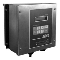
Instructions for mounting the sanitary VFD controller using mounting clips and bars.
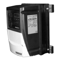
Steps for mounting the industrial VFD controller using mounting bars and T-bars.
Guide for attaching the controller to 2100, 2200, and 3100 series conveyors.
Procedure for mounting the VFD controller onto 6100 series conveyors.
Steps for mounting the controller onto aluminum stand legs.
Instructions for mounting the controller onto steel stand legs.
Covers safety precautions, grounding, and electrical code requirements for controller wiring.
Details default configuration settings for acceleration, deceleration, and frequency.
Information on obtaining replacement parts, referencing the manufacturer's manual.
The Dorner Industrial and Sanitary Variable Speed VFD Controllers are designed for precise speed control of AC motor gearmotors, suitable for both standard and heavy-load applications. These controllers are essential components for optimizing conveyor system performance, offering robust control over motor speed to match various operational requirements. The manual provides comprehensive guidance on the setup, operation, and maintenance of these VFD controllers, ensuring their safe and efficient use in industrial and sanitary environments.
The primary function of the Dorner VFD Controller is to regulate the speed of AC motors used in conveyor systems. By converting fixed-frequency and fixed-voltage AC power into variable-frequency and variable-voltage AC power, the controller allows for precise adjustment of motor speed. This capability is crucial for applications requiring varying conveyor speeds, such as product sorting, assembly lines, or material handling processes where different items may require different transport rates. The controller features a user-friendly interface with a display and dedicated buttons for various functions. These include "Increase Speed," "Start," "Stop," "Decrease Speed," "FWD/REV" (Forward/Reverse), "Enter," "PROG/RUN" (Program/Run), and "AUTO/MAN" (Automatic/Manual) buttons. These controls enable operators to easily adjust and monitor the conveyor's speed and direction, providing flexibility and control over the production process. The "PROG/RUN" button allows users to switch between programming and running modes, while "AUTO/MAN" enables selection between automatic and manual operation, catering to different levels of automation in a facility. The "FWD/REV" button provides immediate control over the conveyor's direction, which can be critical for clearing jams or reversing product flow.
The Dorner VFD Controllers are designed for ease of installation and integration into existing or new conveyor systems. The manual details specific mounting procedures for different conveyor series, including the 2100, 2200, 3100, and 6100 conveyors, as well as for aluminum and steel stand legs. This versatility ensures that the controller can be securely attached in various configurations to suit the physical layout of the workspace. The installation process involves attaching mounting bars and clips to the controller and conveyor frame using hex head screws, ensuring a stable and durable setup. For electrical connections, the controller requires input power connections through a line connection cord grip. The manual emphasizes the importance of proper grounding to prevent injury and advises consulting the AC Tech MC1000 Series Installation and Operating Manual for detailed wiring diagrams and AC requirements. This ensures that the electrical setup is safe and compliant with national and local codes, including the provision of a circuit breaker or disconnect switch with fuses.
The controllers are pre-configured by Dorner when purchased with a gearmotor, with default settings designed for optimal performance. These factory settings include a 1-second acceleration time, a 1-second deceleration time, a minimum frequency of 10 Hz for Sanitary units (6 Hz for Industrial units), a maximum frequency of 60 Hz, and overloads set to the motor's Full Load Amperes (FLA). These default parameters provide a balanced starting point for most applications, allowing for smooth and controlled conveyor operation. Operators can further customize these settings if needed, referring to the AC Tech MC1000 Series manual for advanced configuration options. The intuitive button layout on the controller's front panel allows for straightforward adjustments during operation, making it accessible even for users with limited technical expertise. The display provides real-time feedback on the controller's status and current settings, enhancing operational transparency.
Preventive maintenance and adjustment are critical for ensuring the long-term reliability and performance of the Dorner VFD Controllers. The manual highlights the importance of safety during any maintenance activities, explicitly stating warnings about hazardous voltage and exposed moving parts. Users are instructed to "LOCK OUT POWER" before performing any wiring, removing guards, or attempting adjustments, to prevent severe injury or death. This emphasis on safety underscores the potential risks associated with electrical and mechanical components.
For routine maintenance and adjustments, a flat-blade screwdriver is listed as a required tool. While the manual does not detail specific maintenance tasks for the controller itself, it directs users to the AC Tech MC1000 Series Installation and Operating Manual for additional information on desired settings and replacement parts. This suggests that the controller is designed for minimal direct maintenance, with most service requirements pertaining to the internal components or advanced configurations detailed in the manufacturer's specific manual. The focus on proper grounding as a safety measure also implies that maintaining a secure electrical connection is a key aspect of ongoing care. In case of electrical wiring or troubleshooting needs, users are advised to refer to the information provided by the controller manufacturer, ensuring that expert guidance is followed for complex issues. The availability of service parts is also directed to the AC Tech manual, indicating that specific components for repair or replacement would be sourced according to the drive manufacturer's guidelines.
| Output Frequency | 0-400 Hz |
|---|---|
| Frequency Range | 0.1-400 Hz |
| Enclosure Rating | IP20 |
| Input Voltage | 200-240V AC |
| Protection Features | Overcurrent, Overvoltage, Undervoltage, Overheat, Short Circuit |
| Communication Interface | Modbus RTU (RS-485) |
| Operating Temperature | -10°C to +50°C |
| Storage Temperature | -20°C to +60°C |
| Humidity | 5-95% (non-condensing) |