851-312 Rev. F 5 Dorner Mfg. Corp.
Industrial and Sanitary Variable Speed VFD Controllers
Installation
Required Tools
• Hex key wrenches:
4 mm, 5 mm
• Wrenches 8 mm, 10 mm
• Flat-blade screwdriver
• Torque wrench
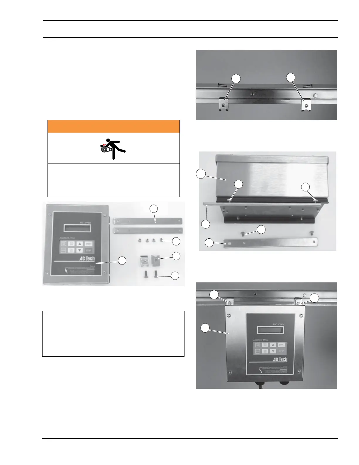
Sanitary Controller Mounting
Figure 2
Figure 2
Installation Component List:
1. Install mounting clips (Figure 3, item B) on conveyor.
Figure 3
Figure 3
2. Attach mounting bars (Figure 4, item C) to controller
(A) with screws (D).
Figure 4
Figure 4
3. Attach controller (Figure 5, item A) to conveyor with
screws (E).
Figure 5
Figure 5
WARNING
Exposed moving parts can cause severe
injury.
LOCK OUT POWER before removing guards
or performing maintenance.
A Sanitary VFD Controller
B 6100 Series Accessory Mounting Clips (2x)
(450186M)
C Controller Mounting Bar (2x) (450333MS)
D Hex Head Screws, M5 x 8mm (4x)
E Hex Head Screws, M6 x 16mm (2x)
B
E
C
A
D
B
B
D
C
C
D
D
A
A
E
E