12
13
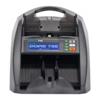
After that, the counter device is ready for counting banknotes at
the following (factory) settings .*
– Interface language – Russian;
– Currency –AUTO;
– Counting mode – ;COUNT
– Start mode– automatic;
– Summation mode – switched off;
– Batching –at the choice;
– Counting speed – 1000 banknotes per minute;
– UV-fluorescence inspection – switched off;
– Display backlight brightness – middle;
– Audio signals – switched off;
– Mode of banknote orientation checking – switched off;
– Stacker capacity – 100 banknotes.
Figure 4 Ready for work screen
4. Adjust the gap of the banknote feed system. The manufacturer
presets the required gap taking into account peculiarities of the
currency to be counted. However, if the counter often stops
during counting, and the display shows the error messages
« » and « », it is necessary to turnDOUBLE ERROR CHAIN ERROR
slightly clockwise « » the screw to adjust thickness of the-
banknotes being counted ( ) (to reduce the gap). Ifsee Fig. 1
either « » or « » appearsNO BANKNOTE LARGE ANGLE ERROR
onthe display after the counter stops, it is necessary to turn slightly
counterclockwise « » the screw to adjust thickness of the+
banknotes being counted ( ) (to increase the gap). Thesee Fig. 1
gap shall allow one banknote to pass freely between the rollers but
prevent two stuck banknotes from passing between them.
5. Install the banknote guides according to the length of the
longest banknote in the batch being counted, level the batch
edges and place it carefully in the middle of the hopper avoiding
its skew.
The counter will start operation automatically.
Counting stops after the number of the banknotes corresponding
to the stacker limit has been counted.
The stacker limit may be set equal to 50 or 100 banknotes. After
the banknotes have been removed from the stacker, the counter
automatically resumes operation.
6. ERRORIn case of an error, follow recommendations of the
MESSAGES Section to eliminate the error.
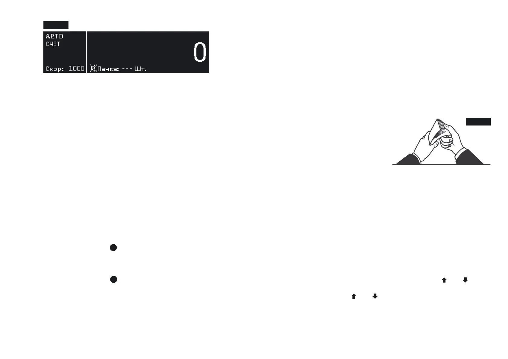
Note:
Prepare the banknotes to
be counted as shown in
Fig. 5;
remove the banknotes that
are torn, wet, grease or
dirty.
Figure 5
* – The factory settings may be changed according to the user’s
requirements.
To enter the user settings menu, hold the key on the controlSET
panel during 1 s ( ). After entering the menu, the left part ofsee Fig.2
the image remains unchanged, and the submenu appears in the right
part. A schematic image of the navigation keys at the right edge of
the display indicates that there will be a jump to another submenu
upon pressing the corresponding key.
To switch between the submenu settings, use the and keys.
To enter the submenu, press the key. Having selected theSET
required setting with the and keys, press the key to enterSET
the settings menu. To exit the user settings menu, hold the keySET
during 1 s. After you exit the menu, the graphical display will show
the selected settings.
MENU SETUP
BANKNOTE COUNTER DORS 750BANKNOTE COUNTER DORS 750
1
1
 Loading...