Pag
4
di
5
Introduction: The residual current devices, type A/AC Dossena DER4 series, fully compliant with IEC 60947-2: 2019, can be used in LV network in AC, TT and TN type. The series offers a wide
range of adjustment of the I∆n threshold (up to 30 A) and of the delay time (up to 30s). DER4 guarantees ease of use, reliability, and speed of programming. The measures and parameters
are clearly displayed. The variation of the background colour immediately indicates the instrument’s operating status (Green = residual current protection active, Blue = setup, Red = Alarm /
Intervention).
INSTALLATION SUGGESTIONS AND SAFETY PRECAUTION:
All installation and maintenance operations must be carried out by qualified personnel in the absence of voltage and in a total electrical safety regime, in compliance with the safety
regulations.
1) Before powering the DER4, check that all connections have been executed properly.
2) ALWAYS install DER4 by using Dossena toroid D series.
3) The cross-section of the conductors must be such that the total resistance of each DER4 ↔toroid connections does not exceed 0.5Ω.
4) Minimize the distance connections between DER4 and toroid and keep them away from power cables; use twisted shielded cables, with the shield connected to ground at one point only
(cable section ≥0,5mm2)
5) At the commissioning perform the calibration of toroid, please view section SETUP item CAL.
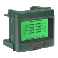
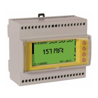
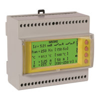
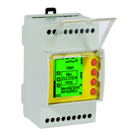
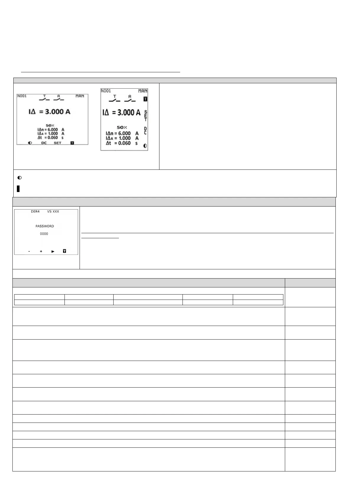
Front-panel version Modular version
The instrument is in the normal state of measurement and supervision. The following parameters are
displayed and continuously updated:
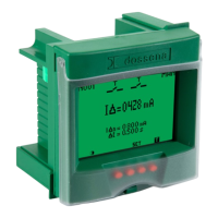
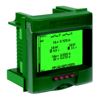
I∆: Visualization in TRMS of the residual current in A.
I∆n= Threshold of the set residual current.
I∆A= Alarm threshold set. (only for models DER4/2D – DER4/2I)
∆t= Limiting non-actuating time.
Reset= automatic (AUTO) or manual (MAN)
State of the relays and their meaning (T trip, A alarm).
Node number, if the serial option is present (es. N001).
If the measured leakage current exceeds the threshold of 25% of the IΔn, the percentage of the
detected current in relation to the set nominal leakage current threshold IΔn will appear flashing on
the display.
The flashing speed will increase as the set threshold value IΔn approaches.
In the event of a trip, the estimate of the maximum measurable tripping current is displayed.
Keys function:
: Press this button to adjust the contrast (once you have changed the contrast, enter and exit setup to save the settings)
SET
: press for at least 3 seconds to enter in SET UP.
T
: pressing the T (Test) button checks the operation of the protection system (DER4 + circuit-breaker opening). Briefly press the TEST button to carry out the test. Soon the display will turn
red, the TRIP relay and the 2nd relay will change state and the word TRIP will appear flashing. If the reset is set to manual
(MAN), pressing the RST key will reset the
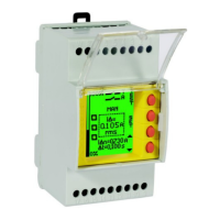
SETUP (blue display)
(in the modular version the keys
are on the right side)
SET = press SET button for at least 3 seconds to enter the SET UP (display becomes blue).
► press to switch from one parameter to another in a cyclical way.
+/- press to modify the selected parameter.
On the toroid type selection page it is possible to start toroid calibration by holding down the CAL key for 2s, in order to eliminate possible offsets.
This operation is absolutely necessary for the instrument commissioning and must be carried out in the total absence of residual current (all loads
must be switched off).
The display will turn green and the message “CALIBRA” will appear. If the calibration is successful the display will return to blue and the message “CAL
OK” will appear, otherwise the display will turn red and the message “FAIL” will appear.
press SET button for at least 3 seconds to exit from SETUP and save the parameters.
DER4 automatically exits from SETUP without saving modifications, after 3 minutes of inactivity.
Note: In the SETUP phase the residual current protection is suspended.
PARAMETERS RANGE
[DEFAULT]
LEVEL IΔn (A)= Threshold of the nominal residual current. The intervention of the TRIP relay will occur when 85% of the set IΔn value is exceeded.
T160/T210/T80S/T60A/T110A/T160A
0,03 ÷ 30A 0,1 ÷ 30A 0,3 ÷ 30A 0,3 ÷ 300A 1 ÷ 30A
0,03 ÷ 30A
[12A]
TORO TYPE= Toroid choice (T35 - T60 - T80 - T110 - T160 - T210 – T80S (adder toroid tranformation ratio CTs ≤ 500/5) – T80SX (adder toroid tranformation ratio
CTs ≥ 600/5) - T300M (multiplier toroid) – T60A – T110A – T160A - T210A - TDRT).
In case of variation of this parameter it is necessary to carry o
ut the calibration procedure
T35 ÷ TDRT [T35]
DELAY ΔT= Limiting non-actuating time (s): delay within which a residual current higher than the set IΔn can flow in the DER4 without causing it to trip
without delay, with instantaneous tripping).
INST/ 0,06 ÷ 30s [5
S
]
ALARM LEV= Alarm threshold. When this threshold is exceeded, an alarm condition is generated. If you want to disable this parameter, set to OFF by holding
down the minus key
−
. If you want the 2nd relay to work as a second trip relay (T), set TT by keeping the plus key
+
pressed (only for models DER4/2D –
OFF/15mA÷85% IΔn/TT
[OFF]
TRIP MODE= It represents the rest state of the TRIP relay. It is normally open (NDE) and closes when the IΔ exceeds the IΔn. In case of NE the letter T will
NDE/NE [NDE]
ALA MODE= It represents the rest state of the alarm relay. It is normally open (NDE) and closes in the presence of alarms. In case of NE the letter A will become
NDE/NE [NDE]
RST MODE= manual or automatic. After a trip for IΔ> IΔn, the message "SET" becomes "RST" and will therefore allow the RESET of the TRIP condition (only if IΔ
<IΔn).
MAN - AUTO [MAN]
BA ALARM= If set to ON, the continuity of the tripping coil and its power supply are constantly monitored, generating an alarm in the event of an anomaly. If
the undervoltage release is used set BA ALARM = OFF.
ON/OFF [ON]
If set to ON, the instrument monitors the possible presence of high and anomalous DC components by generating the relevant fl
nly for versions equipped with serial
and parity bit (N= none, E= even, 0=odd)
nly for versions equipped with serial
PASSWORD= To set the password, enter the chosen number in the relevant field. If a password has already been entered, the display will appear green, the
message SET will become black and it will not be possible to navigate in the setup until the correct password is entered. Once the correct password has been
entered, pressing the SET button for 3 seconds will unlock the setup. Only at this point the display will turn blue and it will be possible to set the parameters
OFF÷ 9999 [OFF]
 Loading...