ALARMS
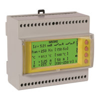
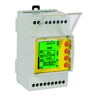
The instrument is able to signal different types of alarms. In presence of general alarm, the
display will turn yellow, the third relay (3R), if it is set will trig and the cause of alarm will be
reported by message in appropriate area (MSG area in the left picture) or by flashing the
greatness that is the cause of mulfunction.
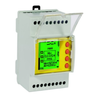
If the resistance falls below the alarm threshold, the display will turn flashing yellow/red
and the alarm relay (A) will intervene (and eventually the third relay, if it is set). If the
resistance falls below the fault threshold, the display will turn red fix and the relay of
FAULT (F) will trig. Below the description of the individual alarms :
ALARM CAUSES
DESCRIPTION ALARM CAUSES DESCRIPTION
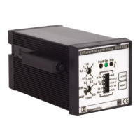
Alarm for resistance
value lower than the set
alarm threshold
The resistance measure will blink and the display
will turn yellow/red flashing.
Disconnection of
measurement connection
to the transformer.
It will appear a blinking message DIS (disconnected)
and the symbol of the transformer.
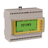
Alarm for voltage
above the maximum
voltage threshold
UMAX.
It will appear a blinking message UMAX
alarm for lower voltage at
the minimum voltage
threshold
UMIN
It will appear a blinking message UMIN
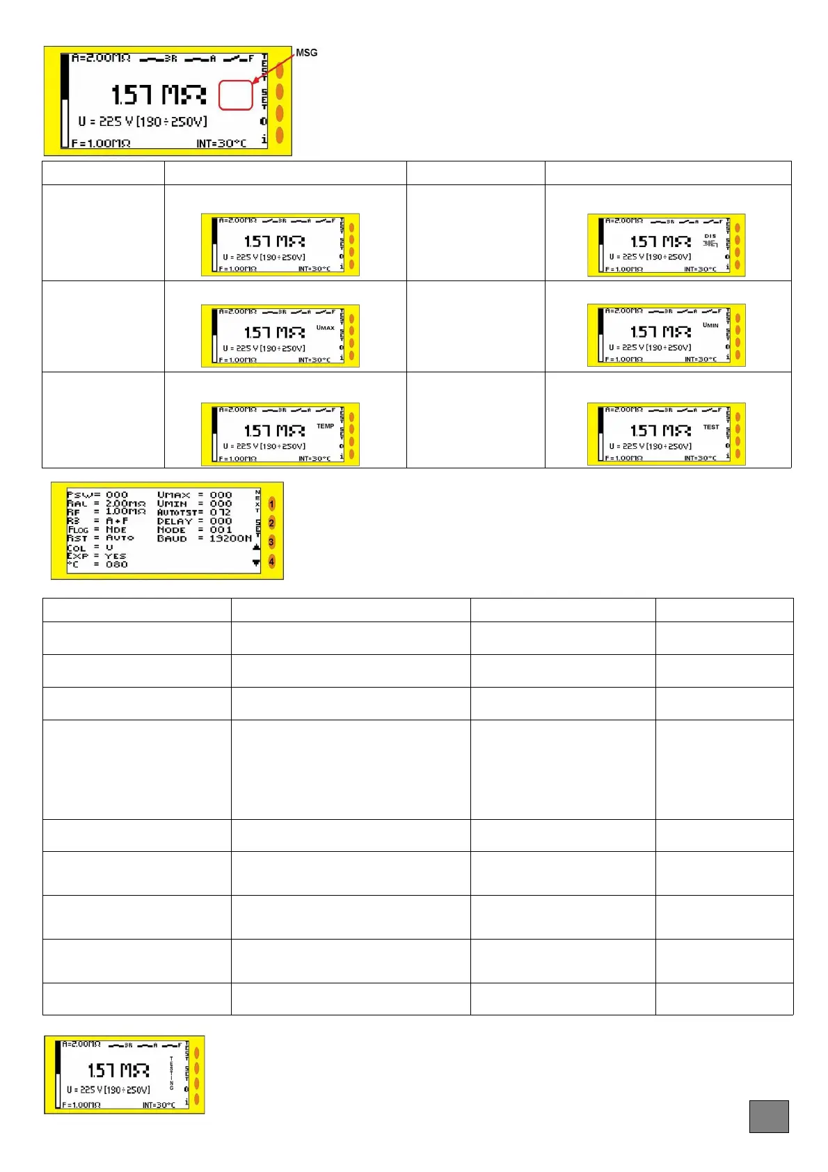
The instrument has
reached an high
internal temperature
It will appear a blinking message TEMP
(temperature).
The device has performed
an automatic and
programmed test but the
test failed
It will appear a blinking message TEST
SETUP MODE
DESCRIPTION RANGE [DEFAULT] DESCRIPTION RANGE [DEFAULT]
PSW = Password setting
000 -999
[default: 000]
UMAX= Overvoltage level for the
alarm of voltage line
0 ÷ 700V
[default: 257]
RAL= Intervention threshold for the
insulation resistance
5kΩ -2MΩ
[default: 200kΩ]
UMIN= Undervoltage level for the
alarm of voltage line
0 ÷ 700V
[default: 203]
RF= Intervention threshold of FAULT
for the insulation resistance
5kΩ -2MΩ
[default: 50kΩ]
AUTOTEST= Time to carry-out a self-
test
0 ÷ 72H
[default: 0]
R3= Function of 3
rd
relay
A+F: if A or F will be on trip
D: it will be on trip, if there is a diagnostic alarms
(temperature, voltage or transformer disconnection)
T: it will be on trip only for temperature alarm
U: it will be on trip only for voltage alarm
DIS: it will be on trip only for alarm of transformer
disconnection
[default: A+F]
DELAY= Delay in seconds for the
tripping of FAULT
0 ÷ 9999 Sec
[default: 0]
FLOG= Resting status (de-energised)
of Fault relay
N.DE./ N.E.
[default:N.DE]
NODE = Number of node on the
network RS485
1- 247
[default: 1]
RST= Reset mode after fault alarm
MAN/AUTO
[default: AUTO]
BAUD= Serial speed and parity bit
(N= none – E = even - 0=odd)
4800-9600-19200-
38400bps
[default: 19200 N]
COL= background color of display in
absence of alarms
G= green B= blue W= white
L= violet N= no color
[default: G]
EXP= Presence of expansion for
networks up to 1000 V
Yes/No
[default: No]
C°=Alarm threshold for the temperature
of internal NTC
0 ÷ 90°C
[default: 0]
Pressing for 3 seconds the SET button, the screen turns blue and you access to SETUP
menu. In Setup the keys have the following meaning:
1: press NEXT to scroll and modify the parameters in a cyclic mode.
2: Press for at least 3 seconds to enter/exit from SETUP function, After 1 minute of inactivity
in SET UP state, the device automatically backs to reading measure, without saving the
parameters changes.
3 e 4: Push to increase or decrease values selected.
The TEST function monitors the correct operation of device. After pressing the TEST button, on the
display will appear the blinking message "TESTING". The instrument will simulate the presence of a
leakage resistance, you will have the tripping of Alarm relay (and optionaly the third relay, if properly
setted) and display will become yellow for few moments then subsequently the tripping of Fault relay
(display will become red). At the end of TEST, the instrument will return in the normal surveillance
conditions, if it is in automatic reset mode.
TEST FUNCTION
EN
 Loading...