Do you have a question about the Dosy TC-4001 and is the answer not in the manual?
Lists power meter scale readings for different watt ranges, from 0-20 Watts to 0-4000 Watts.
Explains why AM modulation should be checked at the transmitter or with the amplifier in standby.
Explains how the TC-4001 Test Center indicates power output and how to set the mode selector switch for measurement.
Provides step-by-step instructions for setting the SWR ratio on the meter.
Details the procedure for checking AM modulation percentage using the test center.
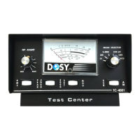
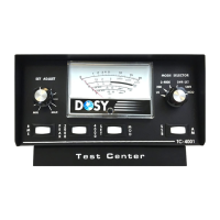
The DOSY TC-4001 Test Center is a versatile instrument designed for monitoring and analyzing the performance of radio transmitters. It serves as an essential tool for radio enthusiasts and professionals, enabling them to ensure their equipment operates efficiently and within optimal parameters. The device primarily functions as a power output meter, a Standing Wave Ratio (SWR) meter, and a modulation checker for both Amplitude Modulation (AM) and Single Sideband (SSB) transmissions. Its comprehensive capabilities allow users to gain critical insights into their transmitter's behavior, facilitating proper setup, tuning, and troubleshooting.
At its core, the DOSY TC-4001 measures the power output of a transmitter in watts. This is crucial for verifying that the transmitter is delivering the expected power levels and for preventing over-powering, which can lead to equipment damage or regulatory non-compliance. The device offers multiple wattage ranges, specifically 20, 200, 2000, and 4000 watts, allowing for precise measurements across a wide spectrum of transmitter outputs. The selection of the appropriate range is made via the Mode Selector Switch, ensuring accuracy and preventing damage to the meter movement.
Beyond power measurement, the TC-4001 incorporates an SWR meter. SWR is a critical indicator of how well an antenna system is matched to the transmitter. A high SWR indicates a mismatch, which can result in power loss, reduced transmission efficiency, and potential damage to the transmitter's final amplifier stage. The SWR function allows users to tune their antenna systems for optimal performance, minimizing reflected power and maximizing forward power. The SWR measurement process involves setting a reference level (SET line) and then switching to the SWR position to read the ratio directly on the meter's scale. This step-by-step approach ensures accurate SWR readings and helps users identify and rectify antenna system issues.
The device also features modulation checking capabilities for both AM and SSB modes. For AM transmissions, the TC-4001 helps users determine the modulation percentage, ensuring that the audio signal is properly superimposed onto the carrier wave without over-modulation or under-modulation. Over-modulation can cause distortion and splatter, interfering with other stations, while under-modulation reduces the effectiveness of the transmitted signal. The AM modulation check involves setting a full-scale reference and then speaking into the microphone to observe the modulation percentage. For SSB transmissions, the device assists in checking the modulation quality, which is vital for clear and intelligible voice communication. SSB modulation is more complex than AM, and proper adjustment is essential to prevent distortion and ensure efficient use of bandwidth. The SSB modulation check involves transmitting in AM mode for setting the meter to a reference point, then switching to SSB and talking or whistling to read the modulation.
The TC-4001 is designed to be installed in-line with the transmitter, meaning it connects between the transmitter and the antenna. This placement allows it to accurately monitor the signals as they travel from the transmitter to the antenna system. The device uses standard RG/58BU coaxial cable connections for input and output, making it compatible with most amateur radio setups. The robust design and clear labeling of controls contribute to its user-friendliness, even for those new to radio operations.
The DOSY TC-4001 is engineered for straightforward operation, with clearly labeled controls and a logical workflow for each measurement function.
Installation: The Test Center can be installed at any point in the transmitter line. It connects to the transmitter's output via the "Input" port and to the antenna via the "Antenna" port, typically using RG/58BU coaxial cable. This flexible installation allows users to integrate it seamlessly into their existing radio setups.
Power Output Measurement (Watts): To measure power, the user first sets the RF Level Control to minimum and the Range Switch to 2000 watts (or 4000 watts if higher power is expected). The Mode Selector Switch is then set to the appropriate wattage range (20, 200, 2000, or 4000 watts). If the power output is uncertain, it is recommended to start with the highest range (4000 watts) and work downwards to prevent damage to the meter movement. This precautionary step is crucial for the longevity of the device. The meter will then display the power output in watts.
SWR Measurement: For SWR measurement, the Mode Selector Switch is turned to the "SWR-SET" position. The SWR RF Level Control is set to minimum. The transmitter is then keyed, and the SWR RF Level Control is turned clockwise until the meter reads full scale to the "Set Line" on the SWR Meter. Once the reference is set, the Mode Selector Switch is moved to the "SWR" position, and the SWR ratio is read directly from the SWR Scale. This process must be repeated for each wattage range to ensure accurate readings and prevent meter damage.
AM Modulation Check: To check AM modulation, the Mode Selector Switch is set to "MOD," and the Set/Modulation rocker switch is set to "SET." The Modulation Mode rocker is set to "AM," and the RF Level control is turned to minimum. The transmitter is keyed, and the RF Level Control is turned clockwise until the meter reads full scale to the "SET line" on the AM Modulation Scale. After setting the reference, the Set/Modulation rocker is switched back to "MOD." The user then talks into the microphone or whistles steadily, and the modulation percentage is read on the AM Scale. Similar to SWR, this check should be performed on each wattage range.
SSB Modulation Check: For SSB modulation, the Mode Selector Switch is turned to "MOD," and the SSB/AM rocker is set to "SSB." For this test, the transmitter must be in AM mode to set the modulation on the meter to the "SET line" on the lower scale marked "SSB MOD." With the transmitter keyed, the mode switch on the transmitter is set to either UPPER or LOWER SIDE BAND. The user then talks or whistles steadily into the microphone, and the modulation is read on the lower scale of the meter, marked "SSB MOD."
Control Layout: The front panel features several key controls:
The intuitive design of the DOSY TC-4001 ensures that users can quickly learn and effectively utilize its features to maintain their radio equipment in top condition. The clear instructions provided in the manual guide users through each step, minimizing the potential for errors and maximizing the utility of the device.
The DOSY TC-4001 is designed for durability and reliable performance, with minimal specific maintenance requirements outlined in the provided documentation. However, general best practices for electronic equipment apply to ensure its longevity and accuracy.
By following these general guidelines and the specific operational instructions provided, users can expect the DOSY TC-4001 Test Center to provide reliable and accurate performance for many years, serving as an indispensable tool in their radio shack.
| Frequency Range | 125 kHz - 200 MHz |
|---|---|
| Power Range | -60 dBm to +20 dBm |
| Accuracy | ±1.5 dB |
| Display | LCD |
| Impedance | 50 Ohms |
| Input Impedance | 50 Ohms |