The DOSY TC-4001-P Test Center is an instruction manual for a device designed to measure power output, Standing Wave Ratio (SWR), and A.M. modulation. It serves as an online version of the DOSY Manual, providing helpful and informative content for users. The device is manufactured by Q. P. Inc., "DOSY METERS," located at 530 E. Lexington Ave. #155, Elkhart, IN 46516, and can be reached at (574) 295-6884 or www.DOSY.com.
Function Description
The DOSY TC-4001-P Test Center is a versatile instrument used to monitor various parameters of radio transmission equipment. Its primary functions include:
- Power Output Measurement (Watts): The device indicates the power output (in watts) of the connected equipment at the point of installation in the transmission line. It supports measurements from 1 to 4000 watts across different ranges.
- SWR Measurement: It allows users to measure the Standing Wave Ratio, which is crucial for ensuring efficient power transfer and protecting equipment.
- A.M. Modulation Check: The unit provides a means to check A.M. modulation percentage, helping users ensure proper signal modulation.
- SSB Modulation Check: It also supports checking SSB modulation, offering comprehensive modulation analysis.
Important Technical Specifications
The manual highlights several key technical specifications and features of the TC-4001-P:
- Wattage Ranges: The device offers multiple wattage ranges for power measurement: 20, 200, 2000, and 4000 watts.
- 0-20 Watts: Uses the 20 Scale.
- 0-200 Watts: Uses the 20 Scale X 10.
- 0-2000 Watts: Uses the 20 Scale X 100.
- 0-4000 Watts: Uses the 4000 Scale.
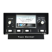
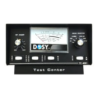
- Controls and Indicators (Figure 1):
- RF Level Control: Adjusts modulation and SWR levels.
- RMS/PEAK Mode Switch: Selects between RMS and PEAK power readings.
- 2000/4000 Watt Range Switch: Toggles between 2000 and 4000-watt ranges.
- SET/MOD Switch: Used for setting modulation or reading modulation percentage.
- Mode Selector Switch: Selects between SWR-SET, SWR, MOD, and other modes.
- Lite Switch: Controls the meter panel lights.
- SSB/AM Mode Switch: Selects between SSB and AM modulation modes.
- Ear-Phone Jack: For connecting headphones.
- Power Requirement: The meter panel lights and headphone jack require the unit to be plugged into a 120-volt outlet using the supplied power adapter.
Usage Features
The manual provides detailed instructions for installing and operating the DOSY TC-4001-P Test Center:
Installation
- The test center can be installed at any point in your transmitter line.
- It connects to the transmitter via an RG/58BU cable, with input, power plug, and antenna connections.
- For the headphone jack and meter panel lights to function, the unit must be powered by a 120-volt outlet using the provided power adapter. The power adapter cable plugs into the power jack on the back of the test center. The "Lite Switch" (#6 Fig. 1) should be set to the ON position to activate the lights.
Starting Tips
- Set SWR and MOD RF level control to minimum.
- Set Range Switch to 2000.
- Set SWR and MOD functions on each Range to prevent damage to the meter movements.
Operating Instructions
Watts Measurement
- Set the Mode Selector Switch (#5 FIG. 1) to the appropriate range (20, 200, 2000 watts) for power measurements from 1 to 2000 watts.
- For wattages larger than 2000 watts, switch the 2000/4000 switch (#3 Fig. 1) to 4000. Remember to switch it back to 2000 when returning to the 2000-watt scale.
- NOTE: If power output is uncertain, always use the highest range first and then work down to an appropriate range to prevent damage to the meter movement.
SWR Set
- Turn Mode Selector Switch (#5 Fig. 1) to the SWR-SET Position.
- Turn SWR RF Level Control (#1 Fig. 1) to Minimum.
- Key the transmitter and turn SWR RF Level Control clockwise (#1 Fig. 1) to achieve a full-scale meter reading on the "Set Line" on the SWR Meter.
- With the transmitter keyed, switch Mode Selector Switch (#5 Fig. 1) to the SWR position and read the SWR ratio directly on the SWR Scale.
- NOTE: SWR functions must be performed on each wattage range to prevent possible damage to the meter movements.
A.M. Modulation Check
- Turn Mode Selector Switch (#5 Fig. 1) to the MOD position.
- Switch Set/Modulation rocker (#4 Fig. 1) to SET.
- Switch Modulation Mode rocker (#6 Fig. 1) to AM.
- Turn RF Level control (#1 Fig. 1) to MIN.
- Key the transmitter and turn RF Level Control clockwise to read full scale to the "SET line" on the AM Modulation Scale.
- With the transmitter keyed, switch SET/MOD rocker (#4 Fig. 1) back to MOD position and talk into the microphone or steadily whistle to read modulation percentage on the AM Scale.
- DO NOT CHECK MODULATION WITH HIGH POWER.
- NOTE: A.M. modulation check functions must be performed on each wattage range to prevent possible damage to the meter movements.
SSB Modulation Check
- Turn Mode Selector Switch (#5 Fig. 1) to the MOD position.
- Switch SSB/AM rocker (#6 Fig. 1) to SSB.
- For this test, the transmitter must be in AM mode for setting modulation on the meter to the "SET line" position. Use the lower scale marked "SSB MOD."
- With the transmitter keyed, turn the Mode Switch on the transmitter to either UPPER or LOWER SIDE BAND and talk or whistle steadily into the microphone. Read modulation on the lower scale of the meter, marked "SSB MOD."
Maintenance Features
The manual includes a "General Notation" section that provides important information regarding the use of the device, particularly with certain types of amplifiers:
- Grounded Grid Amplifiers: The manual advises against checking modulation at higher powers with Grounded Grid amplifiers. These amplifiers may not be able to output 100% modulation in A.M. mode, and the feed-through power can prevent them from being fully modulated. Therefore, A.M. modulation should be checked at the transmitter or with the Linear Amplifier in standby position. This recommendation helps prevent potential damage to the meter movements and ensures accurate readings.