Setting 2 Group
(PRG Button Push for 10 Sec.)
No Menu Code Unit Step Min Max Default Custom Setup
4 0061 Lock Function
LOC
OFF
(0) : Lock cancel
LC
1 (1) : Setting 2 group lock
LC2
(2) : Setting 1,2 group lock
LC3
(3) : Setting 1, 2 group, temp. setup lock
OFF
(0)
4 0062 Sensor Type
IN
TH 1
(0) : DPR-TH01 (-50~105°C)
TH2
(1) : DPR-TH02 (-50~150°C)
420
(2) : 4-20mA signal input
(In case of connecting with press.&humidity sensor)
ST 1
(3) : OUT1 set temperature (
ST1
) display
ST2
(4) : OUT1 set temperature (
ST2
) display
STD
(5) :
ST 1
or
ST2
(
※
1)
TH 1
(0)
4 0063 Max. Sensor Input Range
SH
°C 1
SL 999 10 5
4 0064 Min. Sensor Input Range
SL
°C 1
-199 SH -50
4 0065 Unit of temperature
UNT oC
(0) : Celsius
oF
(1) : Fahrenheit
oC
(0)
4 0066 Decimal Point Display(
※
2)
DP 0. 1
(0) : Decimal point display
1
(1) : Do not display decimals
0. 1
(0)
4 0067 Sensor Correction(
※
3)
COR
°C 0.1
-19.9 19.9 0.0
4 0068 Sensor Input Filter
SFT
Sec 0.1
0.1 5.0 2.0
4 0069 Sensor Value Display Cycle
SDT
Sec 0.1
0 5.0 0.5
4 0070
Operation Cycle Output at Error
Occurrence #1(
※
4)
CL1
Min 1
0 999 OFF
(0)
4 0071
Operation Ratio Output at Error
Occurrence #1(
※
4)
DU1
% 1
0 10 0 50
4 0072
Analogue Trans.
Output(4~20mA) Mode
(-A1 model)
AOM
PV
(0) : Current Temp.
H
(1) : Heating proportional control
C
(2) : Cooling proportional control
ST 1
(3) : Set value Temp.#1
ST2
(4) : Set value Temp.#2
PV
(0)
4 0073 Setup Value Unication Mode (
※
5)
STO
OFF
(0) : Output #1, #2 separation mode
0N
(1) : Unication mode
OFF
(0)
4 0074
Output #2, Select Extended
Function.
(Display
TY2
as
OFF
)
N2
OFF
(0) : Control output operate as the function set at
TY2
T1M
(7) : Timer output
(Regular cycle timer output)
DFH
(8) : Timer output
(Regular cycle timer output : heater defrost)
DFG
(9) : Timer output
(Regular cycle timer output : hot gas defrost)
OFF
(0)
4 0075
Output #2, Timer OFF Time
(Defrost Cycle)
OF2
Min 1
0 999 360
4 0076
Output #2, Timer ON Time
(Defrost Time)
ON2
Min 1
0 999 30
4 0077 Alarm Range High Limit (
※
7)
ALH
- 0.1
ALL SH 30.0
4 0078 Alarm Range Low Limit (
※
7)
ALL
- 0.1
SL ALH - 10
4 0079 Alarm Sensing Hysteresis
AHY
K 0.1
0 99.9 1. 0
4 0080 Communication Address (
※
8)
ADR
- 1
-64 64 1
Automatic reset alarm Manual reset alarm(
※
6)
AL1
(1):
Output ON at sensor alarm +
high limit alarm
AL4
(4):
Output ON & manual reset at
sensor alarm + high limit alarm
AL2
(2):
Output ON at sensor alarm +
low limit alarm
AL5
(5):
Output ON & manual reset at
sensor alarm + low limit alarm
AL3
(3):
Output ON at sensor alarm +
high/low limit alarm
AL6
(6):
Output ON & manual reset at
sensor alarm + high/low limit alarm
(※1)
STD
: Sensor Value Display Value : Display set value of output 1,2 as present value by input ON/OFF.
(※2) Decimal Point Display : Decimal point display : It sets the current value display unit as 0.1/1. i.e. In case of setting as ‘1’, it displays the current value with cutting the decimal place.
(※3) Correct Temp. Sensor : Correct deviations of temperature sensor. e.g) if displayed temperature is 19°C and actual temperature is 18°C, it is corrected by inputting -1.0°C
(※4) Control Output Operation at Error Occurrence : When error occurs, control output repeatedly operates OFF/ON until error is reset.
e.g) In case of setting of operation cycle : 60minutes, ON ratio 20%, it repeatedly operates a cycle of OFF (48 minutes) / ON (12 minutes).
(※5) Setup Value Unication Mode : In case of setting this function as ON, setup value is unied and controlled as 1 case.
(※6) Manual Reset alarm : In case of selecting manual reset alarm, it is reset by re-inputting power or pushing PRG button rapidly 2 times.
(※7) In case of occurrence of high or low limit alarm, it doesn’t aect control output #1 at all.
(※8) Communication Address : Master mode address is to -1 from -64.
Communication Table
No Menu Unit Type Size (Word) FX MMI Scale
4 0101 Product status codes Digital INT 16 Refer to bit status below
Bit 0 Output 1 ON / OFF status Digital Bit 0 : OFF 1 : ON
Bit 1 Output 2 ON / OFF status Digital Bit 0 : OFF 1 : ON
Bit 8 Defrost output ON / OFF status Digital Bit 0 : OFF 1 : ON
Bit 12 Min. range alarm Digital Bit 0 : Normal 1 : Alarm
Bit 13
Max. range alarm
Digital Bit 0 : Normal 1 : Alarm
Bit 14 Sensor (disconnection, short-circuit) Alarm Digital Bit 0 : Normal 1 : Alarm
Bit 15 EEPROM alarm Digital Bit 0 : Normal 1 : Alarm
4 0102 Current temperature value (PV) °C Analog INT 16 -50 ~ 105 -500 ~ 1050 1/10
4 0103 FND display current temp. value (PV) °C Analog INT 16 -50 ~ 105 -500 ~ 1050 1/10
4 0104 Output 1 (
ST1
) settings (
*
read only) °C Analog INT 16 -50 ~ 105 -500 ~ 1050 1/10
4 0105 Output 2 (
ST2
) settings (
*
read only) °C Analog INT 16 -50 ~ 105 -500 ~ 1050 1/10
4 0107
Command of compulsory defrost with manual
Analog INT 16 1 : START (Auto-reset)
4 0108
Command of compulsory defrost termination
Analog INT 16 1 : STOP (Auto-reset)
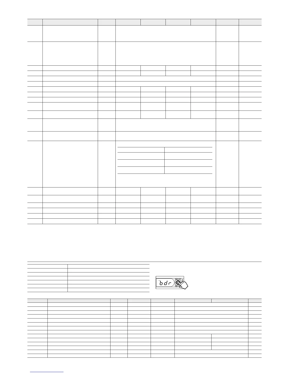
Change of BPS
Default value of this model is 4800bps and it should be changed separately.
1. Entry into parameter relating to BPS
Press
PRG
+
SEL
+ ▲ + ▼ buttons simultaneously
for 5 seconds as shown in the figure
2.
BDR
BDR Communication Speed (Press the SEL button eight times)
Adjust BPS using ▲ / ▼ buttons from the
BDR
parameter
(
48
: 4800bps,
96
: 9600bps,
19 2
: 19200bps,
384
: 38400bps)
3. Store set value (Press the SEL button for three seconds)
Transmission line connection Multiple line
Communications method RS485 (2-wire, half-duplex)
BPS BPS default 4800 BPS
Parity, Data, Stop bit None, 8 Data, 1 Stop
Protocol Type Modbus RTU Mode
Function Code Read HOLD REGISTERS (0x03) / Preset Single Register (0x06)
Poll interval 100msec
Communication
FX3D
OUT1
OUT2
 Loading...