D
Danielle LevyAug 10, 2025
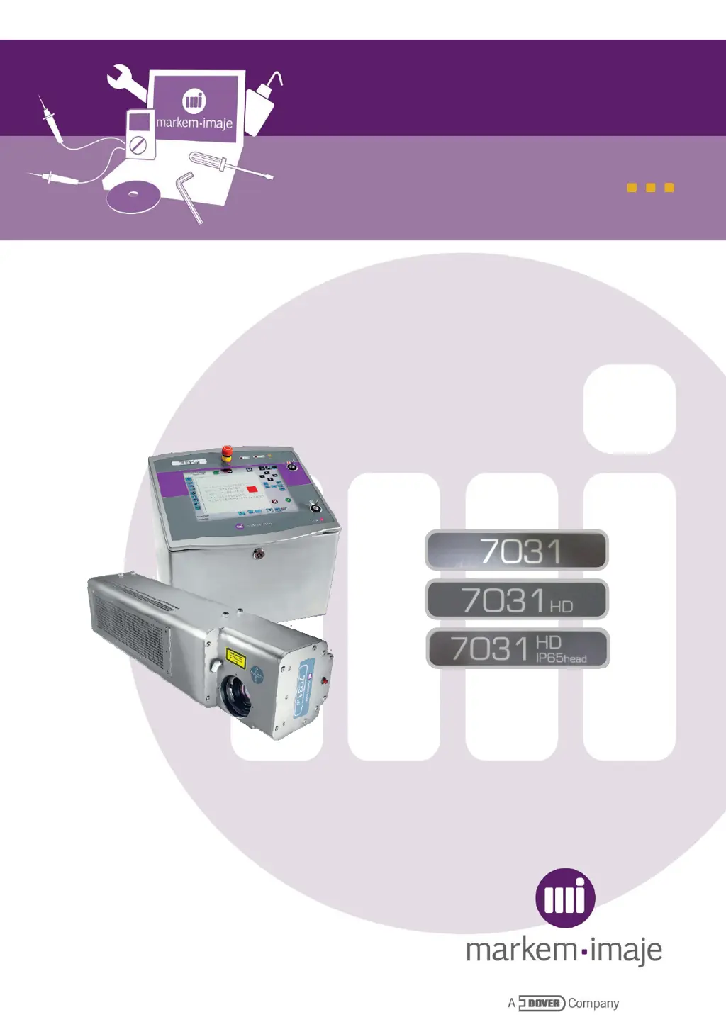
Why is the marking quality bad on my Dover Markem-Imaje LASER 7031 HD?
- MMichael AndersonAug 10, 2025
If the marking quality is poor (weak marking) on your Dover Controller, several factors could be at play. First, ensure that your marking parameters are suitable for the substrate. If power loss is less than 15%, check and clean the focal lens for any dust or oil. Also, verify the vacuum nozzle position, placing it as close as possible downstream of the marking. Confirm that extractor filters aren't blocked and the vacuum level is sufficient. Make sure the IP65 air pressure is sufficient and dried, and that the IP65 air pressure pipe is optimal. If there is no power loss, it may be out of focus or the marking parameters are not correct. Finally, adjust laser settings in advanced settings (power adjustment).