Do you have a question about the Dover MagLink LX4 and is the answer not in the manual?
Defines DANGER, WARNING, CAUTION, NOTICE, SAFETY INSTRUCTIONS for hazard communication.
Explains the meaning of NOTE, IMPORTANT, REMINDER, TIP, and INFORMATION panels used in the manual.
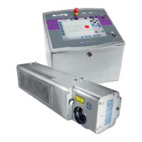
Details console components, technical characteristics, and available ports for connection.
Critical safety warnings for console installation in hazardous areas.
Guidance on selecting a suitable, safe, and protected installation location.
Procedures and safety for connecting the console to a 220 VAC power supply.
Step-by-step instructions for physically mounting and preparing the console.
Wiring details for connecting Intrinsically Safe XMT-SI and DMP-SI probes.
Wiring details for connecting XMT Explosion-proof probes to the console.
Wiring details for connecting the RF Receiver to the console.
Identifies console connectors and their specifications for relay interfaces.
Information regarding the optional IFSF module installation and connectivity.
Explains the function and configuration settings of the DIP-Switch block.
Information on the Micro SD card's role and handling precautions.
Steps for closing the console and initiating the startup sequence.
Details DB9 connections to various fuel management systems like DIALOG, GILBARCO, DRESSER.
Safety warnings and important notices regarding console maintenance and cleaning procedures.
Guidelines for communicating with technical support and exporting log files via USB.
Provides a wiring diagram for connecting XMT-SI probes to the console.
Illustrates the wiring diagram for connecting XMT Exd probes.
Shows the wiring diagram for connecting RF probes to the console.
Details the wiring diagram for connecting On/Off Sensors with the I/O Module.
| Brand | Dover |
|---|---|
| Model | MagLink LX4 |
| Category | Controller |
| Language | English |