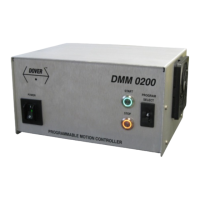
The DMM-0200 is a programmable motion controller designed to control stepper motors, offering a versatile and efficient solution for a wide range of motion control requirements. It is part of a family of controllers that can manage up to four axes of motion, with the DMM-0200 specifically supporting one or two step axes. Additional axes (up to four) are available with the DMM-0400 controller.
Function Description
The DMM-0200 serves as a central unit for controlling stepper motors, enabling precise and programmable motion. It can be operated in two primary modes:
- PC Controlled: The DMM-0200 can be controlled via a PC using a USB connection and the PMX-2EX-SA software. This software provides a graphical user interface (GUI) for running and programming the controller. Users can also communicate with the DMM-0200 through USB using other software like LabVIEW or MATLAB, utilizing ASCII commands.
- Stand-Alone Operation: The DMM-0200 can function independently without external communication. Motion can be initiated using the front panel START and STOP buttons, along with a PROGRAM SELECT thumbwheel to choose from stored programs.
The controller supports both trapezoidal and S-curve velocity profiles for motion control. Trapezoidal profiles are the default, while S-curve profiles can be enabled using the SCV[axis] command.
Important Technical Specifications
- Power: The DMM-0200 requires a main power source with a voltage range of 90-264VAC ± 10% and a frequency of 47-63 Hz. The typical maximum inrush surge current is no more than 11 amps at 110VAC nominal voltage. A NEMA 5-15 receptacle is required in North America, with a dedicated 1.2kVA power line and ground recommended.
- Dimensions (maximum):
- Width: 24.06 cm (approx. 9.47 inches)
- Depth: 20.05 cm (approx. 8.08 inches)
- Height: 12.86 cm (approx. 5.06 inches)
- Weight: 2.24 Kg (approx. 4.95 lbs)
- Operating Environment:
- Temperature: 15-30˚ C (59-86˚ F)
- Relative humidity: 20-80% non-condensing
- Altitude: 0 to 2,000 meters above sea level (0 to 6,600 feet above sea level)
- Connectivity:
- USB: USB 2.0 compliant for communication with a PC.
- Serial: Two DE-9-M connectors (J4-SERIAL X, J21-SERIAL Y) for serial data communications to individual axis drivers.
- Encoder/Limits: Two HD-15-F connectors (J10-ENC/LIM X, J24-ENC/LIM Y) for encoder and limit switch inputs. Supports both single-ended and differential quadrature encoders with a maximum frequency of 5MHz.
- Motors: Two DE-9-F connectors (J11-MOTOR X, J26-MOTOR Y) for stepper motor connections.
- Encoder Out: One DA-15-M connector (J25-ENC OUT X/Y) for encoder outputs for both axes.
- Digital I/O: One DB-25-F connector (J18-DIGITAL I/O) for 8 opto-isolated digital inputs and 8 digital outputs.
- Analog I/O & Joystick: One DA-15-F connector (J19-ANALOG I/O JOYSTICK) for 8 x 10-bit analog inputs (0-5000 mV range) and joystick connection.
- Programming Language: The DMM-0200 uses an ASCII-based programming language for standalone programs and interactive commands. It supports conditional statements (IF, ELSEIF, ELSE), loops (WHILE, ENDWHILE), subroutines (SUB, GOSUB, ENDSUB), and various motion control commands (e.g., X, Y, JOG, HOME, ABORT, STOP).
- Memory: Standalone programs can have a memory size of 1,275 assembly lines.
- Multi-Threading: Supports simultaneous execution of up to two standalone programs (Program 0 and Program 1) controlled via SR0 and SR1 commands.
Usage Features
- Front Panel Control: The front panel includes a POWER switch, START and STOP buttons for initiating and halting motion programs, and a PROGRAM SELECT thumbwheel to choose from up to 10 stored programs (0-9).
- Software Interface (PMX-2EX-SA): The GUI provides a "Main Control Screen" for comprehensive motion control, including:
- Status Screen: Displays current pulse position, encoder position, speed, motor status (Idle, Accel, Const, Decel), StepNLoop value, delta value, limit/home input status, and Z encoder index channel status.
- Control Screen: Allows setting global high speed, low speed, and acceleration, selecting X/Y axes for synchronous movement, entering target positions, enabling driver power, and executing homing routines (Home input only, Home and Z-index, Z-index only, Limit only).
- On-The-Fly Speed/Position Control: Enables real-time adjustment of speed and target position during motion.
- Digital I/O Status: Visualizes the status of digital inputs and outputs, and analog input values.
- Program File Control: Tools to open, save, compile, download, and upload standalone programs.
- Variables: Displays current values of variables, some of which can be stored to flash memory.
- Homing Routines: Five different homing routines are available, utilizing home, limit, and Z-index switches to establish a zero position.
- Jogging: Continuous speed operation for moving axes in positive or negative directions.
- StepNLoop Closed Loop Control: Features a closed-loop position verification algorithm using an incremental encoder. It performs position verification at the end of moves and delta monitoring during moves to detect and correct errors.
- Joystick Control: Allows controlling pulse speed and direction using corresponding analog inputs, with configurable maximum speed, speed change delta, and zero tolerance range. Soft limits (negative outer/inner, positive inner/outer) are also available.
Maintenance Features
- Fuse LEDs: Rear panel LEDs indicate the status of fuses for each axis (X and Y). An illuminated green LED indicates the fuse is okay, while a non-illuminated LED indicates a blown fuse.
- Enable LEDs: Rear panel LEDs indicate whether each axis (X and Y) is enabled. An illuminated green LED indicates the axis is enabled.
- Error Handling: During standalone execution, if an error occurs (e.g., limit error), the program automatically jumps to a reserved subroutine (SUB 31). If SUB 31 is not defined, the program ceases execution. The controller also provides error codes for various communication and command-related issues.
- Buffer Flushing: For USB communication issues, a
fnPerformaxComFlush function is available to clear USB buffers on both the PC and the device, helping to re-synchronize data.
- USB Cable Recommendation: It is recommended to use a USB cable with a noise suppression choke to prevent communication issues.
- Parameter Storage: Device settings and the second half of general-purpose variables (V32-V63) can be permanently stored to flash memory using the STORE command, preserving them after a power cycle.
- Device Number Modification: The unique device number can be modified and stored to flash memory using the DN command.