EasyManua.ls Logo

Dover DMM-0200 - Table 11 Pinouts - Encoder out X & y; Table 12 Pinouts - Digital I;O

Dover DMM-0200
112 pages
Print Icon
To Next Page IconTo Next Page
To Previous Page IconTo Previous Page
Loading...
Page 27 of 112
DMM-0200 Product User Guide
159 Swanson Road
Boxborough, MA 01719
Tel: 508-475-3400
Email: sales@dovermotion.com
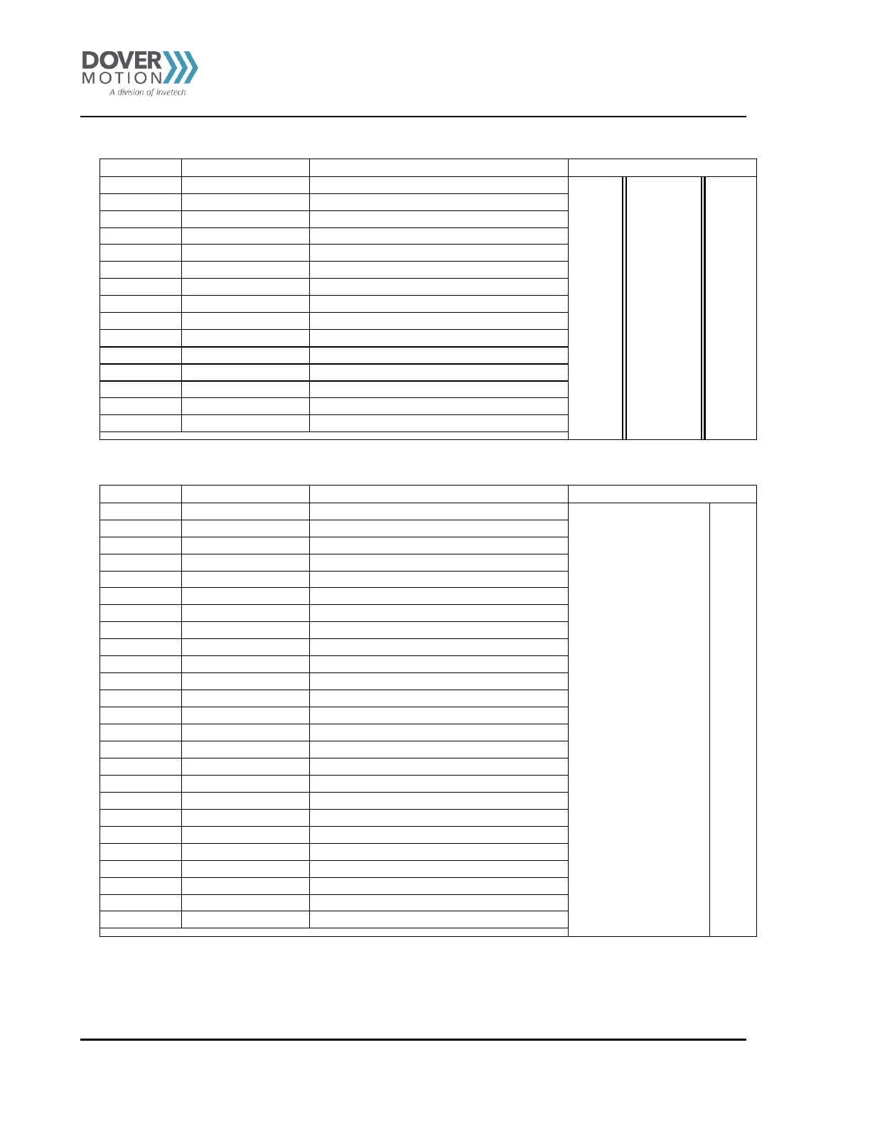
Pinouts Encoder Out X & Y (J25-ENC OUT X/Y)
Pin Number
Function
Description
DA-15-M Connector
1
ENC AY
Y axis Encoder A channel
7
15
8
1
2
ENC /AY
Y axis Encoder /A channel
3
ENC BY
Y axis Encoder B channel
4
ENC /BY
Y axis Encoder /B channel
5
ENC ZY
Y axis Encoder Z channel
6
ENC /ZY
Y axis Encoder /Z channel
7
N/C
8
ENC /ZX
X axis Encoder A channel
9
ENC ZX
X axis Encoder /A channel
10
ENC BX
X axis Encoder B channel
11
ENC /BX
X axis Encoder /B channel
12
ENC /AX
X axis Encoder Z channel
13
ENC AX
X axis Encoder /Z channel
14
GND
Ground
15
GND
Ground
Table 11 Pinouts Encoder Out X & Y
Pinouts Digital I/O (J18-DIGITAL I/O)
Pin Number
Function
Description
DB-25-F Connector
1
+OPTO LIM
Opto limit power (+5VDC)
1
14
25
13
2
+OPTO I/O
Opto I/O power (+5VDC)
3
+12V INT
+12VDC
4
OPTO GND
Logic ground
5
OPTO GND
Logic ground
6
DIG IN1
Digital Input 1
7
DIG IN2
Digital Input 2
8
DIG IN3
Digital Input 3
9
DIG IN4
Digital Input 4
10
DIG IN5
Digital Input 5
11
DIG IN6
Digital Input 6
12
DIG IN7
Digital Input 7
13
DIG IN8
Digital Input 8
14
DIG OUT1
Digital Output 1
15
DIG OUT2
Digital Output 2
16
DIG OUT3
Digital Output 3
17
DIG OUT4
Digital Output 4
18
DIG OUT5
Digital Output 5
19
DIG OUT6
Digital Output 6
20
DIG OUT7
Digital Output 7
21
DIG OUT8
Digital Output 82
22
RELAY N.C.
Relay N.O. connection
2
23
REALY N.O.
Relay N.C. connection
2
24
RELAY COM
Relay common
2
25
SHIELD
Chassis ground
Table 12 Pinouts Digital I/O
2 Jumper JP1 enables and disables the relay function through digital output 8. Please see Jumper section for detailed
description of the functionality.

Table of Contents

Related product manuals