Page 48 of 112
DMM-0200 Product User Guide
159 Swanson Road
Boxborough, MA 01719
Tel: 508-475-3400
Email: sales@dovermotion.com
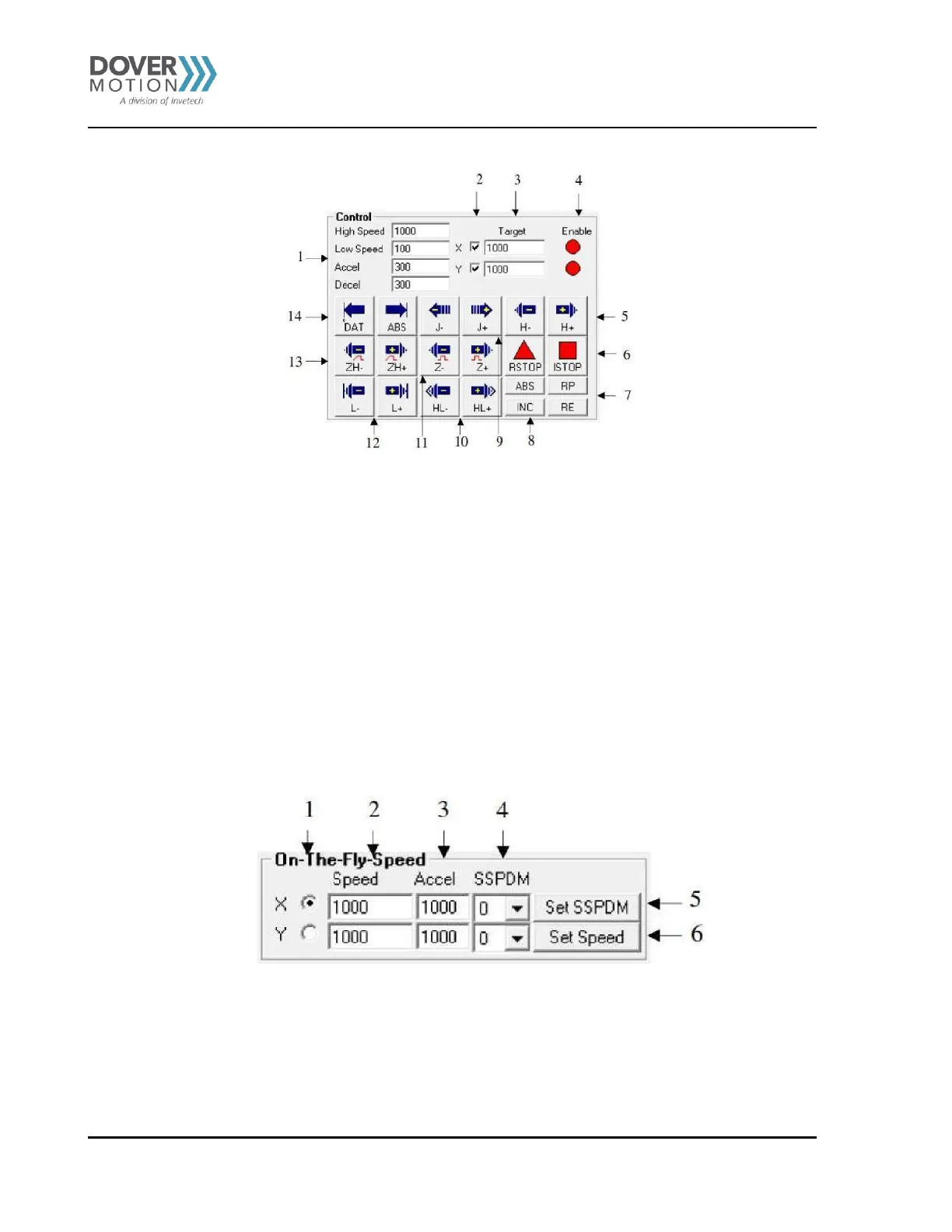
Figure 16 Status Screen (B)
1. Global high speed, low speed, and acceleration values are entered here (X/Y axis). To give each axis individual speed
parameters, enter HSPD[axis], LSPD[axis], and ACC[axis] into the command line in the “Terminal” section.
2. Select X/Y axis. Selection of both axes will result in synchronous movement.
3. Target position entered here (X/Y axis).
4. Enable driver power for the indicated motor (X/Y axis).
5. H+/H- – Home the motor at high speed using only the home sensor.
6. RSTOP/ISTOP – Stop the motor with deceleration using RSTOP. Stop the motor immediately using ISTOP.
7. RP/RE – Reset the position/encoder position.
8. ABS/INC – Set the move mode to absolute or incremental.
9. J+/J- – Jogs the motor in the positive or negative direction.
10. HL+/HL- – Home the motor at high speed and low speed using only the home sensor.
11. Z+/Z- – Only encoder index channel used for homing.
12. L+/L- – Home the motor using only the limit sensor.
13. ZH+/ZH- – Both encoder index and home sensor used for homing.
14. DAT/ABS – Move the motor to position zero by using DAT. Move the motor to the target position by using ABS.
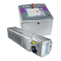
On-The-Fly-Speed Control (C)
Figure 17 On-The-Fly-Speed Control (C)
1. Select X/Y axis.
2. Select destination speed of the axis.
3. Select the acceleration used during an on-the-fly speed change.
4. Select the SSPD mode for the axis. See On-The-Fly Speed section for details.
5. Set the SSPD mode for the axis.
6. Set on-the-fly speed change. Acceleration will be taken from the “Accel’ field.