Page 99 of 112
DMM-0200 Product User Guide
159 Swanson Road
Boxborough, MA 01719
Tel: 508-475-3400
Email: sales@dovermotion.com
Enable Outputs
The enable output status can be controlled using the EO command. EO value must be within the range of 0-3.
Enable output values can also be referenced one bit at a time by the EO[1-2J commands.
Note that the indexes are 1-based for the bit references (i.e. EO1 refers to bit 0, not bit 1)
Table 26 Enable Outputs
The initial state of the enable outputs can be defined by setting the EOBOOT register to the desired initial
enable output value. The value is stored to flash memory once the STORE command is issued.
Analog Inputs
2 x 10-bit analog inputs are available on PMX-2EX-SA. Use AI[1-2] command to read the analog input
value. Range is from 0-5000 mV.
Joystick Control
Joystick control is available on PMX-2EX-SA. When this mode is enabled, the pulse speed and direction output
can be controlled by corresponding analog input. See the axis to analog input relationship in the table below:
Table 27 Joystick Control
Maximum joystick speed is set using the JV1 and JV2 variables.
Maximum speed change (delta) is set using the JV3 and JV4 variables.
Tolerance of the zero joystick position, use JV5 and JV6 variables.
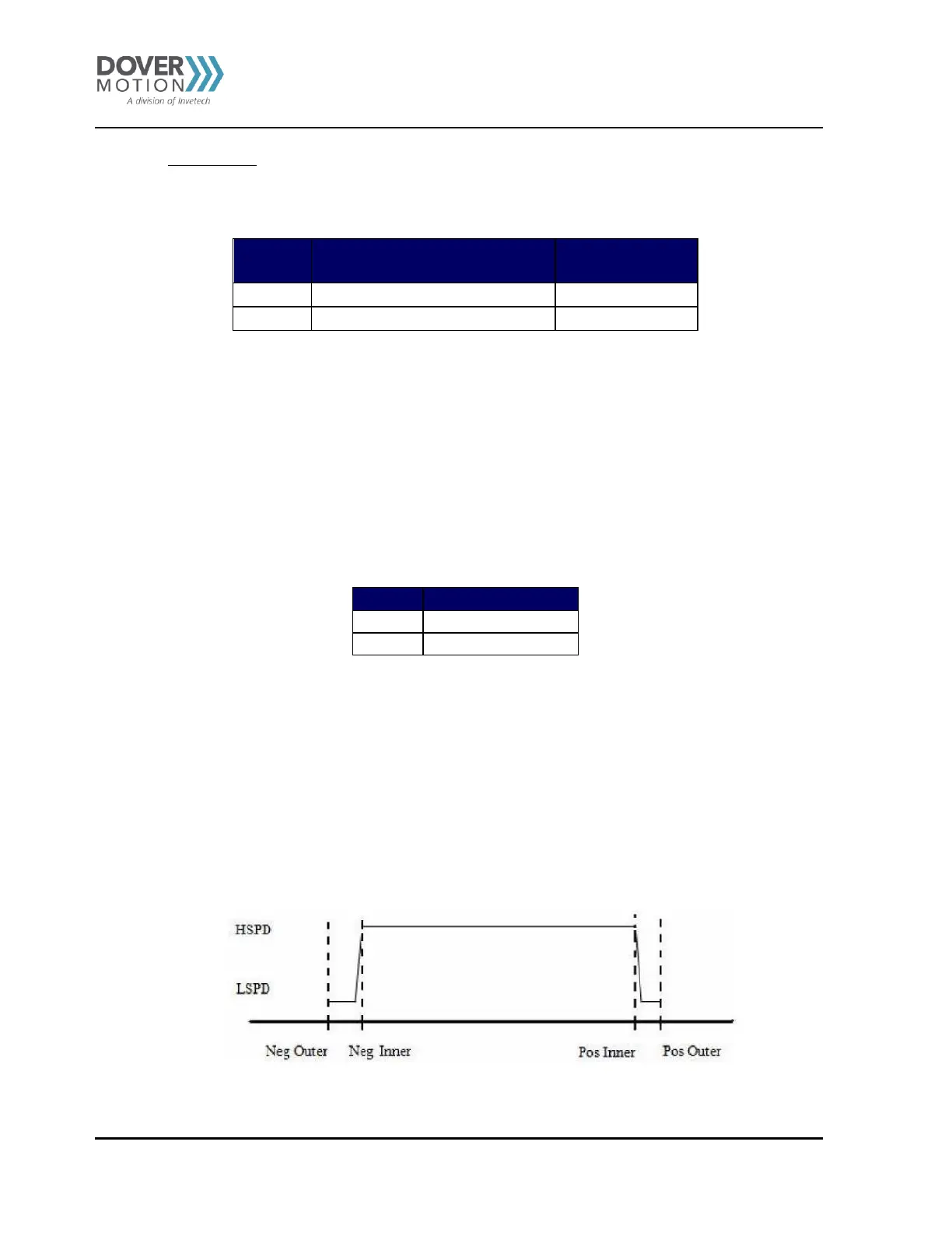
Joystick control also has soft limit controls. Limits are broken into: negative outer limit, negative inner limit,
positive inner limit and positive outer limit.
When moving in positive direction, as soon as the positive inner limit is crossed, the speed is reduced. If the
position reaches the positive outer limit, the joystick speed is set to zero. Same goes for the negative direction
and negative limits.
The behavior of the limits of the joystick control is explained by the following:
Figure 40 Joystick Control