Page 28 of 112
DMM-0200 Product User Guide
159 Swanson Road
Boxborough, MA 01719
Tel: 508-475-3400
Email: sales@dovermotion.com
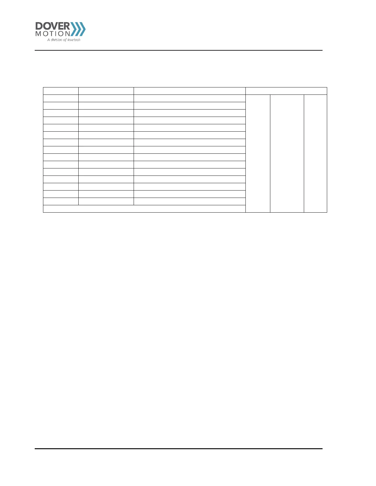
Pinouts – Analog I/O & Joystick (J19-ANALOG I/O JOYSTICK)
Joystick - Stick pushbutton, Digital input 1
Joystick X analog input, Analog input 1
Joystick Y analog input, Analog input 2
Joystick - Left pushbutton
3
, Digital input 2
Joystick Z analog input, Analog input 3
Joystick - Right pushbutton
4
, Digital input 3
Table 13 Pinouts – Analog I/O & Joystick
3 Jumper JP8 enables and disables the left pushbutton control from the joystick. Please see Jumper section for detailed
description of the functionality.
4 Jumper JP7 enables and disables the right pushbutton control from the joystick. Please see Jumper section for detailed
description of the functionality.