Page 32 of 112
DMM-0200 Product User Guide
159 Swanson Road
Boxborough, MA 01719
Tel: 508-475-3400
Email: sales@dovermotion.com
Interface Circuitry
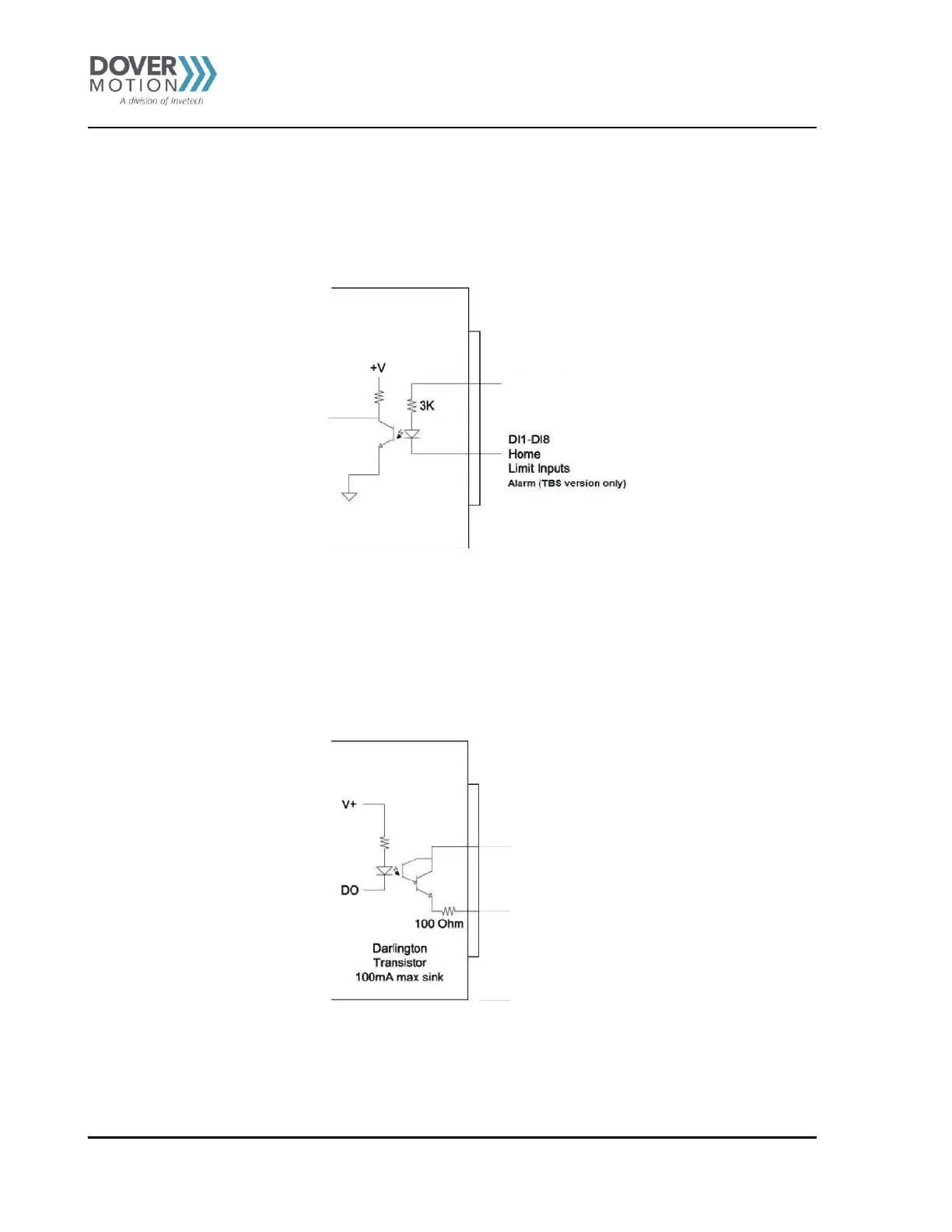
Limit, Home, and Digital Input
To trigger the opto-isolated digital inputs, sink the digital input signal to the ground of the corresponding opto-supply.
Note: Alarm input for TB9 version is 5V TTL type.
Figure 5 Digital Inputs
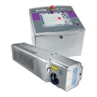
Digital Outputs
For the opto-isolated outputs, the digital output signal will source from VS when the signal is turned on.
Figure 6 Digital Outputs