RZN 4404-M / 08-K / 08-M RZN 4404-M / 08-K / 08-M
99.822.96 3.1/09/1399.822.96 3.1/09/13
26/36 27/36
Cables for D+H smoke an heat vent systems
When selecting and installing the cables, the
regional electrical installation regulations
concerning wiring systems and the necessary
safety equipment, or guidelines on integrity
maintenance of electric lines are observed (e.g.
MLAR).
Notice:
No type designation is given for these cables,
because of a large variety on the market.
Please consult your D+H partner.
Wiring plan (Paragon)
Group cable (control panel - drive)
At least three wire design:
- 2 wires for the supply of the drive
- 1 wire for line monitoring, on which also the
SHEV high speed (HS) signal is transmitted to the
drive. If group DIP switch 7 is ON, the group will in
case of a fault automatically triggered and opens.
Line cable (control panel - detector)
The cables are monitored for short circuit and for
interruption. If line DIP switch 3 is ON, the group
will in case of a fault automatically triggered and
opens.
Line lenghts and cross sections
Cross section (mm²) =
Cable lenght (m) x Total current
80
RZN 4408-M / RZN 4408-K
RZN 4404-M
1
120
200
2
60
100
3
40
65
4
30
50
5
24
40
6
20
33
7
17
28
8
15
25
m
m
Type
Total current
3 x 1,5 mm²
3 x 2,5 mm²
230 V, 50 Hz
Seperate electric circuit.
Mark fuse.
to further ones
see line lenghts and cross sections
Drive at smoke
vent opening
SHEV control panel
Vent button
approx. 1,2 m
above upper edge
firm flooring
Smoke vent button
approx. 1,5 m above
upper edge firm flooring
External control
Fire detector
FO 1362 or FT 1262
4x 0,8 Ø
6x 0,8 Ø (RT 45)
10x 0,8 Ø (RT 45-LT)
6x 0,8 Ø (RT 45)
10x 0,8 Ø (RT 45-LT)
2x 0,8 Ø
2x 0,8 Ø
OK
OK
Rain detector
3x 0,8 Ø
System voltage 24 V!
Do not run cables with together power lines!
In case of a cable with ground wire (green /
yellow) this must not be used!
Cable and terminal boxes have to be labeled.
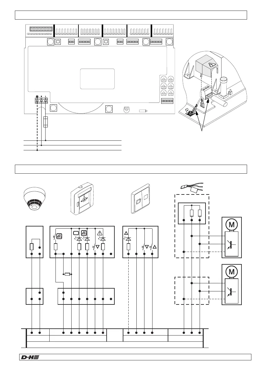
Connection overview
230 V, 50 Hz
Seperate electric circuit..
Mark fuse.
230 V supply
Protective earth (PE)
Only with -KS and -MS Version.
Protection cap:
Place enclosed protection cap
over supply terminal after mains
cable has been connected.
L
N
X15
L
N
PE
2
8
3 1 6 4 7
5
RT 45
2
7
4
FO 1362
2 8 3 1 6 4 7
5
RT 45
2 8 3 1 6 4 7
5
OK
Line
T
R
– A– K EA aZ bS
RZN 440x-M / RZN 4408-K
Line
–
N–
Control
Alarm
CLOSE
Mot.b
Mot.a
Monitoring
OPEN
CLOSE
Open signal (only with LT
43U-SD)
RM LT
10kW
Failure
Alarm
Control
–
Line
CLSOE
Failure
n.c.
RT MOT
2
7
FO 1362
10kW
4
OK
L N– Z
LT 84-U (-SD)
L
P
EM 47 K
2x47kW
(BK)
(BK)
(OG)
Mot.b
Mot.a
HS
Drive
Mot.b
Mot.a
HS
English English
 Loading...