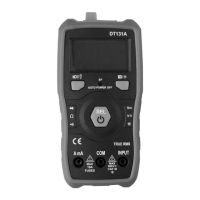
DT131A
7
NCV / – non-contact voltage measurement / ashlight
– function remembering the last measurement (HOLD) / display
backlight
A mA SOCKET: gauging socket, to be connected with the red "+" cable (am-
perage) measurement
COM SOCKET: gauging socket, to be connected with the black "-" cable
INPUT SOCKET: gauging socket to be connected with the red "+" cable
selected measuring function
type of measured voltage: AC, DC
low battery indicator
ashlight indicator
HOLD function indicator
NCV indicator
ashlight
NCV probe
AC/DC voltage measurement
1. Connect the red testing cable to INPUT socket , and the black cable to
COM socket .
2. Hold down the button for min. 1 s to turn on the meter. The display
will show "- - - -".
3. Press the button to select the DC or AC measurement function .
4. Attach gauging cables to measured circuit or device.
5. Read voltage value on the display .
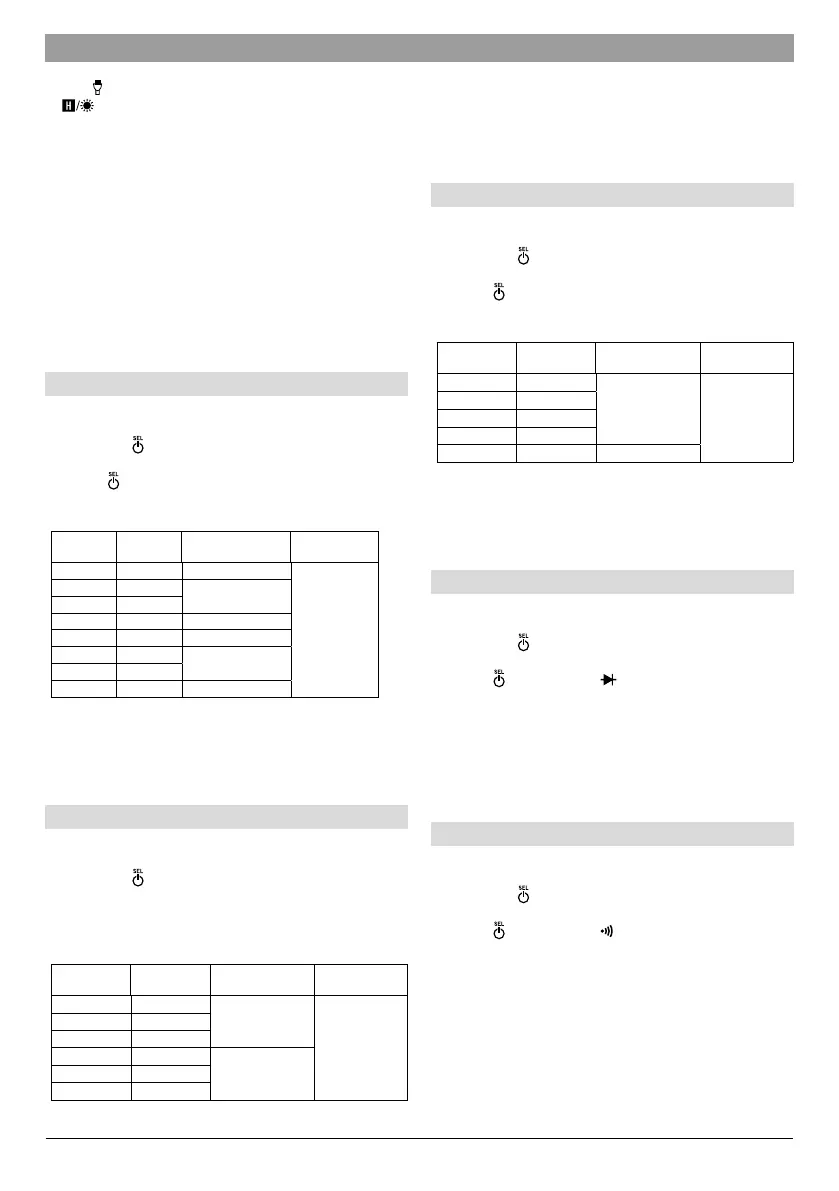
Range Resolution Accuracy Overload protection
Frequency: 40–400 Hz
DC 600 mV 0.1 mV ±0.8% + 5 digits
600mV
range: 250V AC/
DC rms
DC 6 V 1 mV
±0.8% + 3 digits
DC 60 V 10 mV
DC 600 V 1 V ±1.0% + 5 digits
AC 600 mV 1 mV ±(1.2% + 5 digits
AC 6 V 1 mV
±(1.0% + 8 digits
AC 60 V 10 mV
AC 600 V 1 V ±(1.2% + 8 digits
When measuring DC voltage, the meter shows the polarity with the
red test lead Voltage measurements below DC 200 mV and AC 500
mV may be inaccurate or indicate errors Never perform the meas-
urement of current if open circuit voltage to earth exceeds 600 V.
AC/DC amperage measurement
1. Connect the red testing cable to A mA socket , and the black cable to
COM socket .
2. Hold down the button for min. 1 s to turn on the meter. The display
will show "- - - -".
3. Open the circuit, in which amperage will be measured and attach gauging
cables to the gauged circuit.
4. Read amperage value from the display .
Range Resolution Accuracy
Overload
protection
DC 60 mA
10 A
±1.2% + 8 digits
fuse
F 10 A / 600 V
DC 600 mA
100 A
DC 10 A 10 mA
AC 60 mA
10 A
±1.5% + 8 digits
AC 600 mA
100 A
AC 10 A 10 mA
When measuring DC amperage, the meter shows the polarity with
the red test lead Amperage measurements below AC 20 mA may be
inaccurate or indicate errors Measurement time < 15 s (min.15
min interval) Amperage measurements > 5 A - measurement time
< 10 s (min. 15 min interval).
Resistance measurement
1. Connect the red testing cable to INPUT socket , and the black cable to
COM socket .
2. Hold down the button for min. 1 s to turn on the meter. The display
will show "- - - -".
3. Press the button to select measurement function .
4. Attach gauging cables to resistor that will be measured.
5. Read current’s amperage from the display .
range
Resolution Accuracy
Overload
protection
600 0.1
±1.5%+3 digits
250 V AC/DC
Maximal open circuit
voltage: 0.25 V
6 k 1
60 k 10
600 k 100
60 M 100 k
±3.0%+10 digits
Prior to resistance measurement the circuit’s power supply must be
switched off and all capacitors discharged For resistance meas-
urements > 10 M, the meter needs a few seconds to display the
correct result.
Diode test
1. Connect the red testing cable to INPUT socket , and the black cable to
COM socket .
2. Hold down the button for min. 1 s to turn on the meter. The display
will show "- - - -".
3. Press the button to select measurement function .
4. Attach the red gauging cable to anode and black cable to cathode of gauged
diode.
5. Read diode’s conducting voltage on display . By reversed cables a “OL”
shall be displayed.
Maximum open circuit voltage: 1.5 V Overload protection: 250 V
AC/DC
Circuit continuity test
1. Connect the red testing cable to INPUT socket , and the black cable to
COM socket .
2. Hold down the button for min. 1 s to turn on the meter. The display
will show "- - - -".
3. Press the button to select measurement function .
4. Attach gauging cables to measured circuit.
Continuity of the circuit shall be flagged with an audio signal when
resistance is l< 50 With a resistance of 50-100 , the acous-
tic signal may not appear With a resistance > 100 the acous-
tic signal does not appear Maximum open circuit voltage: 0.5 V
Overload protection: 250 V DC / AC
 Loading...