CONTACT US AT www.DRpower.com 7
Grader Box
ssembly
2
3
5
Figure 3
4
1
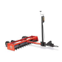
Specifications
Teeth
12-Tungsten Carbide-Tipped 4142 Hardened Alloy Steel
Mold Board
Cold Rolled 1018 Steel 3-Gauge (.2391")
Wheels
Flat free- Solid Rubber, 8"X3.00"-4"/2.25"
Hitch Height Range
3.63" to 13.922"
Tooth length below frame rails
.8"
Number of revolutions to raise teeth 1" in
8
Weight capacity (blocks)
80lbs (2 standard 16"x8"x8" cinder blocks)
Control Box Heights
36.862"to 38.862" from tow bar
Control Box post Angle
90degrees,75degrees and 60 degrees
Control Box adjustable location
Sliding control box post for different tow vehicles
1/2" Shear Pin
Protects against tow vehicle damage
Reversible Scraping Blade (Mold Board)
Grading or grooming blade types
Adjustable Angle Scraping Blade (Mold Board)
50degrees,90degrees,105degrees (50 for aggressive cutting,90 for light
Drag Screen
Optional drag screen
Minimum Tow Vehicle HP
14 hp or 400 lb. lawn tractor or garden tractor
Hitch Type
Pin or Ball
Dim's (assembled)
68"X49"X44"
Weight (Grader without weights)
126LBS
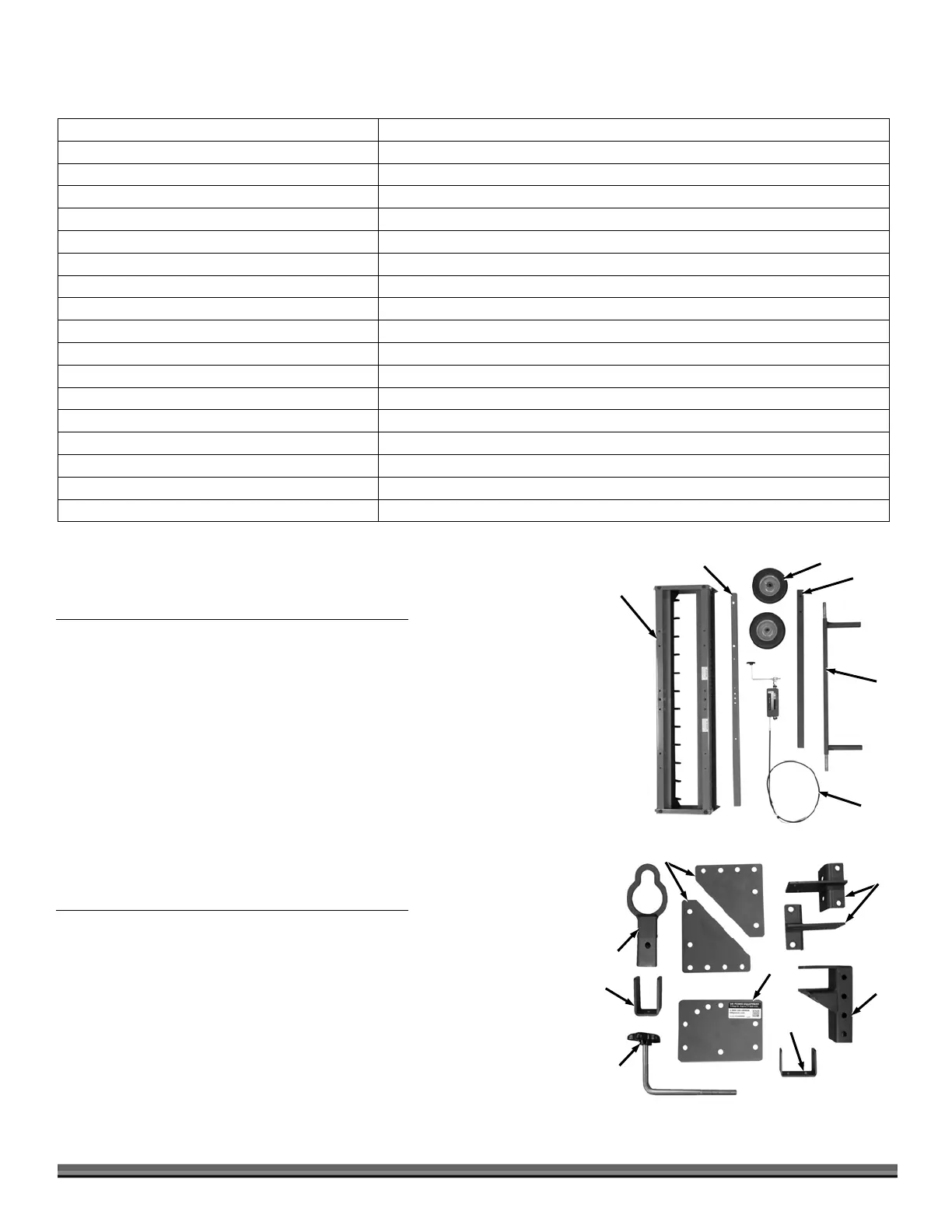
Main Parts (Figure 3 and Table below)
Description Qty
1 ........... Tow Bar .........................................................1
2 ........... Wheels ...........................................................2
3 ........... Crank Post .....................................................1
4 ........... Axle Assembly ...............................................1
5 ........... Height Adjust Control Box Assembly 1
Parts Box (Figure 4 and Table below)
Description Qty
1 ........... Bracket, Hitch Adjustment ...........................2
2 ........... Bracket, Axle ..................................................2
3 ........... Hitch Assembly, Pin ......................................1
4 ........... Bracket, Spring, Cable ...................................1
5 ........... Plate, Backing, U-bolt, Sliding ......................1
6 ........... Bracket, Anti-Rotation, Hook, Tow ...............1
7 ........... Hitch, Tow Hook ...........................................1
8 ........... Crank Handle ................................................1
1
Figure 4
2
3
4
6
5
7
8