Installing 2
nd
Gas Spring
Tools and Supplies Needed:
• 1/2 Wrench if necessary
• 13mm Wrench or Adjustable Wrench if necessary
1. At this point you can now install the 2
nd
gas spring. With the cable
connected to the eyebolt, pull the Dump Lever while pushing down
on the cart bed. With the lever pulled, guide the Bed/Collector until
the cable is taught
(
Refer to “Dumping” pg. 33
).
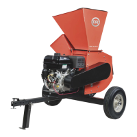
2. With the cart bed open, install the 2
nd
gas spring by pressing the Gas
Spring onto the Studs with the larger end of the Gas Spring attached
to the Frame and the thin Shaft end to the Cart Bed. If the Gas Spring does not line up to the studs, you can loosen the stud
using a 1/2” Wrench and a 13mm or Adjustable Wrench (Figure 57). With the stud loose, it will allow for easier installation.
Once the Gas Spring is installed, re-tighten the stud using the same wrenches.
Installing the Hose
Tools Needed:
• Wire Cutters
• Black Marker
• Utility Knife
• Flat Head Screwdriver or 7mm Wrench
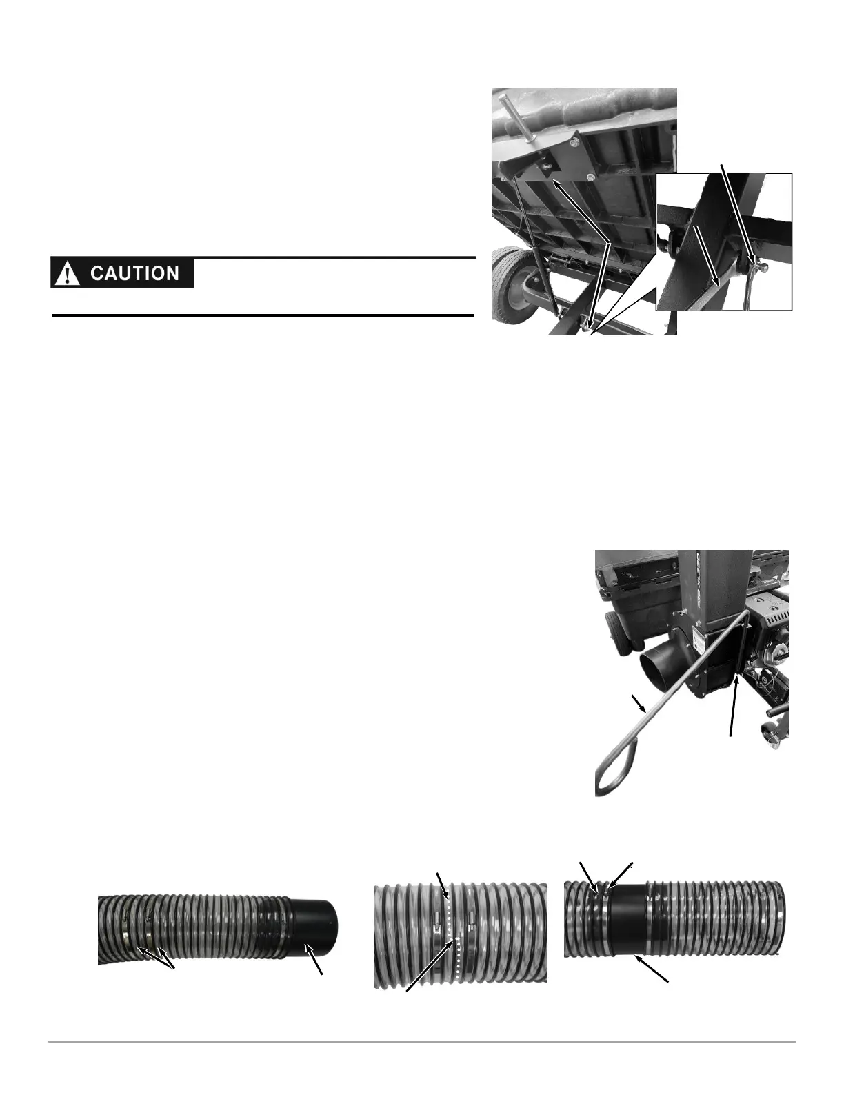
1. If not already done, unhitch the Cable Link from the Impeller Housing Bracket by
turning the hex portion of the link to open it up.
2. Slide the Hose Support into the Impeller Housing Bracket holes (Figure 58).
3. Locate the two Bridge Hose Clamps near the Coupling end of the Hose Assembly
(Figure 59).
4. Cut the black Spiral Rib of the Hose between the two clamps using Wire Cutters (Figure
60). Do not cut the clear area of the Hose yet.
5. Mark the path where you will cut the clear Hose using the black Marker to ensure that
the cut will meet at the opposite side.
6. Cut the clear area Hose where you marked using the Utility Knife to separate the short
Hose/Coupling section from the longer Hose/Cuff section.
7. Flip the Hose/Coupling section around, Loosen the Hose Bridge Clamp at the end of
the longer Hose and slide the Coupling into the Hose until the Clamp is just past the
Rivet (Figure 61).
8. Tighten the Bridge Hose Clamp onto the coupling using a Flat Head Screwdrive
or 7mm Wrench.
 Loading...