EasyManua.ls Logo

Dräger PAS AirPack - User Manual

Dräger PAS AirPack
3 pages
Print Icon
To Next Page IconTo Next Page
Loading...
PAS
®
AirPack
Pneumatic Assembly
Instructions for Use
i
PAS
®
is a registered trademark of Dräger 3357744 (A3-D-P) Page 1 of 3
1 For your safety
1.1 General safety statements
Before using this product, carefully read the Instructions for Use.
Strictly follow the Instructions for Use. The user must fully understand
and strictly observe the instructions. Use the product only for the
purposes specified in the Intended Use section of this document.
Do not dispose of the Instructions for Use. Ensure that they are
retained and appropriately used by the product user.
Only fully trained and competent users are permitted to use this
product.
Comply with all local and national rules and regulations associated
with this product.
Only trained and competent personnel are permitted to inspect, repair
and service the product. Dräger recommends a Dräger service
contract for all maintenance activities and that all repairs are carried
out by Dräger.
Properly trained service personnel must inspect and service this
product as detailed in the Maintenance section of this document.
Use only genuine Dräger spare parts and accessories, or the proper
functioning of the product may be impaired.
Do not use a faulty or incomplete product, and do not modify the
product.
Notify Dräger in the event of any component fault or failure.
The air supply shall meet the requirements for breathing air according to
EN12021.
1.2 Definitions of alert icons
Alert icons are used in this document to provide and highlight text that
requires a greater awareness by the user. A definition of the meaning of
each icon is as follows:
WARNING
Indicates a potentially hazardous situation which, if not avoided,
could result in death or serious injury.
CAUTION
Indicates a potentially hazardous situation which, if not avoided,
could result in physical injury or damage to the product or
environment. It may also be used to alert against unsafe practices.
2 Description
2.1 Product overview
The Dräger PAS
®
AirPack Pneumatic Assembly is a pressure reducer and
gauge set that uses breathing air inputs to provide a medium-pressure output
(independent air supply) for one or two breathing apparatus wearers, or for
pneumatic tools or equipment.
Breathing air inputs are from high-pressure and/or medium-pressure
sources. The high-pressure input is from one or two breathing air cylinders.
The medium-pressure input is a regulated external supply from a factory
airline or compressor.
Referring to Fig 1, the features and components of the Pneumatic
Assembly are:
The high-pressure input connectors (7) are standard cylinder-type
threaded connectors.
The medium-pressure input connector (9) is a male quick connector
which has an internal non-return valve.
The output connector (4) is a female quick connector, which has a
valve that self-seals when disconnected.
A high-pressure gauge (1) indicates cylinder pressure.
A medium-pressure gauge (2) indicates output pressure.
A high-pressure whistle (10) sounds to indicate low cylinder pressure.
A medium-pressure whistle (3) sounds to indicate low output pressure.
If the Pneumatic Assembly is using an external medium-pressure
supply, the whistle indicates that the external supply pressure is low.
An internal pressure reducer converts the high-pressure input to a
medium-pressure output.
A relief valve (5) in the medium-pressure system and bleed valves (8)
on the high-pressure connectors release air from the system when
operated.
The Pneumatic Assembly is available as a one-cylinder or two-cylinder
version. The two-cylinder version allows the user to remove depleted
cylinders and replace them with fully charged cylinders when required.
Repeatedly replacing alternate depleted cylinders can provide an
uninterrupted air supply to the attached breathing apparatus wearers.
Internal non-return valves (Fig 1, Item 6) ensure that air from the other
cylinder can not escape when a depleted cylinder is removed.
Holes in the corners of the front plate can be used to secure the Pneumatic
Assembly. The holes are: approximately 6.2 mm diameter; and
approximately 155 x 210 mm between centres.
2.2 Intended use
The Pneumatic Assembly is used with breathing air cylinders and an
external breathing air supply (works airline or compressor) to provide a
medium-pressure output. When used with approved Dräger airline
equipment, it supplies breathing air to one or two breathing apparatus
wearers.
It is intended to be used with only the air cylinder(s) connected (self-
contained use), or with the air cylinder(s) and an external medium-
pressure supply connected (external-supply use). When it is used with an
external supply the cylinders provide a backup air supply.
The breathing apparatus, cylinders and other accessories used with this
product must be certified Dräger components assembled in an approved
configuration. See Section 10 for the compatible airline equipment and
configurations. Contact Dräger for further information.
2.3 Approvals
The European standards, guidelines, and directives according to which
this product is approved are specified in the declaration of conformity (see
declaration of conformity or www.draeger.com/product-certificates).
2.4 Use in potentially explosive atmospheres
The PAS AirPack Series is type tested as suitable for use in potentially
explosive atmospheres. The combinations are suitable for use in
hazardous areas of Zone 1 and 2 for explosion group IIA and IIB and for
Zone 21 and 22.
!
!
2.4.1 Special conditions for safe use
The Airline Systems shall not be used in the vicinity of processes where
high charges are generated if explosive atmospheres are present (for
example, where rapid filling processes are carried out – big bag filling – or
many actions of fast limit surface separation are done). In such cases,
hazardously high charges of the Airline Systems may occur due to
electrostatic induction.
The breathing apparatus and the compressed air cylinders which are used in
combination with the Airline Systems each have to meet the applicable
requirements of the equipment categories and explosion groups relevant to
the respective Airline System.
The Airline Systems have to be moved manually inside explosive
atmospheres by the user (pushing or pulling). It is mandatory to use floors
in Zone 1 and Zone 21 that are able to discharge electricity where dusts of
minimum ignition energies < 10 mJ are present.
If air supply hoses are used with a total length > 50 m, then the couplings which
are connected to the hoses in a conductive manner have to be provided with
an additional earth contact (after a hose length of 50 m) and integrated into the
operating eqipotential bonding.
Do not charge the cylinder in a potentially explosive atmosphere.
2.5 Explanation of marking and symbols
Refer to the relevant authority for explanation of approval body symbols
and markings. Examples of other marking on the product:
BRBA-1359 Dräger serial number
08/09 Month and year of manufacture
3353261 Dräger part number
HP High pressure
MP Medium pressure
Medium-pressure input
Medium-pressure output
Relief valve
Where appropriate, the marking “F” on the apparatus and CAST
(compressed-air supply tube) indicates that both can be used where
flammability may be a risk. Marking on the compressed-air supply tube
indicates that the tube is heat resistant (H) and/or antistatic (S).
3 Use
WARNING
The cylinder and airline air quality shall meet the requirements for
breathing air according to EN 12021. Do not use oxygen or
oxygen-enriched air. The moisture content of breathing air should
be controlled within the EN 12021 limits to avoid freezing the
apparatus.
Carry out a risk assessment of the workplace to ensure that it is
not possible to connect to any airline supply other than breathable
air (e.g. Nitrox).
Before using airline equipment, ensure that the air supply meets
the air quality requirements, and complies with the airline
pressure, flow and hose requirements (see Section 8 and Section
10), and has been issued with a permit for use if necessary.
Position the Pneumatic Assembly in a safe and uncontaminated
area, and ensure that it is securely held or placed in a position
where it cannot be damaged.
Dräger recommend that the user carries out a risk assessment to
establish local procedures to be followed in the event of failure of
the air supply.
!
CAUTION
Impact damage to the Pneumatic Assembly may prevent cylinder
valve connection or cause an air leak. Handle the equipment with
care.
When remote wearers are connected to the Pneumatic Assembly, a
controller must be appointed to monitor the gauges and whistles of the
product throughout the operation. The controller must maintain the air
supply to the wearers and must ensure that any precautionary or
emergency signals are conveyed to the remote wearers in line with local
procedures and these Instructions for Use.
3.1 Preparation for use
1. Carry out a visual inspection (see Section 3.4.1).
2. Connect the air cylinder or cylinders (see Section 3.4.2).
3. Carry out a full functional test (see Section 3.4.5).
WARNING
Incorrect airline equipment configurations may result in insufficient
air flow to breathing apparatus wearers or increase the possibility
of air supply failure. See Section 10 for the compatible airline
equipment and configurations.
Prepare the breathing apparatus for use (see the Instructions for
Use supplied with the breathing apparatus). Observe the safety
information and carry out all preparation and functional testing
tasks before use.
Do not use the Pneumatic Assembly to supply air to more than two
breathing apparatus wearers at any time. If a controller is
appointed, and is required to wear breathing apparatus and to
connect to the equipment then only one other user is permitted.
4. Connect the airline equipment (extension hoses, Y-piece, etc.) to the
medium-pressure output connector (Fig 2).
5. Depending on the required use, do one of the following:
Self-contained use – Fully open the cylinder valve (open only one
cylinder valve on a two cylinder version).
External-supply use – Connect the external supply (see
Section 3.4.4). Ensure that cylinder valves are fully closed.
6. Put on the breathing apparatus and connect to the airline equipment
(Fig 3 shows a typical breathing apparatus connector).
3.2 During use
WARNING
An appointed controller or the breathing apparatus wearers must
monitor the Pneumatic Assembly gauges and whistles during use.
Procedures to warn and evacuate remote users must be in place.
The effective working duration of the equipment is dependent on
the initial air supply available and the breathing rate of the wearers.
Do not commence any operation using a cylinder that is less than
80 per cent full.
At very high work rates the pressure in the face mask of a
breathing apparatus wearer may become negative at peak
inhalation flow.
Breathe normally and proceed to the work area taking care with any
airline equipment.
On receipt of an evacuation signal, withdraw immediately to a safe
area (see local instructions for full evacuation procedures).
When the task is complete, withdraw to a safe area before removing
the breathing apparatus.
The high-pressure and medium-pressure whistles indicate that there is
low pressure in the associated system. If a warning whistle sounds,
carry out the necessary actions depending on the configuration of the
Pneumatic Assembly (see Sections 3.2.1 or 3.2.3).
3.2.1 Medium-pressure whistle sounds during external-supply use
Fully open one cylinder valve, and disconnect the external supply from the
Pneumatic Assembly. Continue the task as a self-contained use task.
3.2.2 Medium-pressure whistle sounds during self-contained use
Breathing apparatus wearers must proceed in line with breathing
apparatus Instructions for Use and local procedures.
3.2.3 High-pressure whistle sounds during self-contained use
If there is a second/offline fully-charged cylinder connected to the
Pneumatic Assembly, proceed as follows:
a. Fully open the valve of the second/offline cylinder.
b. Close the valve of the empty cylinder and then open its bleed valve.
c. If a replacement cylinder is available, immediately remove the
empty cylinder (see Section 3.4.3) and fit a replacement (fully
charged) cylinder (see Section 3.4.2).
If the second/offline cylinder is empty, or there is no second/offline
cylinder connected: breathing apparatus wearers must proceed in line
with breathing apparatus Instructions for Use and local procedures.
3.3 After use
WARNING
Do not remove the breathing apparatus until in a safe breathing
environment.
1. Once in a safe area, remove all breathing equipment.
2. Disconnect the external supply from the Pneumatic Assembly and fully
close all cylinder valves.
3. Pull the handle of the relief valve (Fig 1, Item 5) to vent all air from the
system.
4. Disconnect any airline equipment from the Pneumatic Assembly and
fit all protection caps.
5. Disconnect the air cylinders if necessary (see Section 3.4.3).
6. Carry out the after use maintenance tasks in the maintenance table
(see Section 5.1).
3.4 Common user tasks
3.4.1 Visual inspection
Check that the Pneumatic Assembly is clean and undamaged, paying
particular attention to pneumatic components, hoses and connectors.
Typical signs of damage that may affect the operation of the Pneumatic
Assembly include impact damage, abrasion, cutting, corrosion and
discolouration. Report damage to service personnel or Dräger and do not
use the Pneumatic Assembly until faults are rectified.
!
!
!
!
3
4
1
10
6
7
5
9
2
8
1
3222
3228
2
3248
3
3226
4
2
3
1
3227
5

Other manuals for Dräger PAS AirPack

Question and Answer IconNeed help?

Do you have a question about the Dräger PAS AirPack and is the answer not in the manual?

Summary

General Safety

Safety Warnings

Highlights critical safety information and general precautions for using the equipment.

PAS AirPack Pneumatic Assembly Overview

Use of the Breathing Apparatus

Instructions on how to correctly operate the breathing apparatus.

Use in Hazardous Areas

Specific guidance for using compressed air from Zone 1 or Zone 2 hazardous areas.

Connecting and Disconnecting Air Supply

Connecting Air Cylinders

Steps for securely connecting approved breathing air cylinders.

Functional Testing

Performing Functional Tests

Step-by-step guide to conduct essential functional tests for system integrity.

Maintenance

Maintenance Table

Outlines service and testing tasks for the pneumatic assembly with frequencies.

Technical Data

Compatible Airline Equipment

Lists compatible external air supply equipment and connection types.

Overview

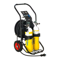
The PAS® AirPack Pneumatic Assembly is a robust and versatile device designed to provide a reliable supply of breathing air for multiple users in various demanding environments. Its primary function is to serve as a centralized breathing air supply system, allowing two or more breathing apparatus wearers to connect simultaneously and receive a continuous flow of medium-pressure air. This makes it particularly suitable for situations where extended duration breathing air is required, such as in industrial settings, confined spaces, or during emergency response operations.

Function Description

The core function of the PAS® AirPack is to regulate and distribute medium-pressure breathing air from an external source to individual breathing apparatus. It features multiple output connectors, typically four, allowing up to two breathing apparatus wearers to connect directly to the unit. For scenarios requiring more than two wearers or greater flexibility, extension hoses and stand-alone hose reels can be integrated, expanding the system's reach and capacity. The device is designed to operate with either a factory airline or a compressor as its input source, ensuring adaptability to different site conditions.

A critical aspect of its functionality is the integrated pressure management system. The unit includes a medium-pressure input, which is then distributed to the output connectors. Each output is equipped with a quick-connect coupling, facilitating easy and secure attachment of breathing apparatus. The system incorporates safety features such as pressure gauges to monitor the input and output pressures, and a relief valve to prevent over-pressurization. This ensures that the air supplied to the wearers is within safe and effective operating parameters.

The assembly is designed for both stationary and mobile use. Its robust construction allows it to be deployed in challenging environments, while its modular design supports various configurations, from direct connections to extended hose setups. This flexibility ensures that the PAS® AirPack can meet the diverse needs of different operational scenarios, providing a dependable breathing air supply for extended periods.

Usage Features

The PAS® AirPack is designed for ease of use and quick deployment. Connecting breathing apparatus is straightforward, thanks to the quick-connect couplings on the output connectors. Users simply attach their breathing apparatus to the available output, and the system is ready to deliver air. The clear labeling of connectors and intuitive design minimize the risk of errors during setup.

For scenarios requiring extended reach, the system supports the use of extension hoses and stand-alone hose reels. These accessories can be easily integrated, allowing wearers to move further away from the main unit while maintaining a continuous air supply. This is particularly beneficial in large industrial complexes or during rescue operations where mobility is crucial. The ability to connect multiple wearers simultaneously enhances team efficiency and safety, as it eliminates the need for individual air cylinders for each person, reducing logistical burdens.

The device also features a robust chassis, often made of durable materials like stainless steel, which protects the internal components from damage in harsh environments. This ensures the unit's longevity and reliability, even with frequent use in demanding conditions. The compact design of the main unit, despite its multi-user capability, allows for relatively easy transport and positioning.

Before use, a thorough functional test is recommended to ensure all components are working correctly. This includes checking the pressure gauges, verifying the integrity of all connections, and ensuring the relief valve operates as expected. The clear instructions provided in the manual guide users through these pre-use checks, promoting safe and effective operation.

Maintenance Features

Regular maintenance is crucial for ensuring the continued reliability and safety of the PAS® AirPack. The system is designed with several features that facilitate easy inspection and servicing. Key components, such as hoses, couplings, and pressure gauges, are accessible for visual inspection and functional checks.

A comprehensive maintenance schedule is recommended, including periodic visual inspections, functional tests, and component replacements. For instance, hoses and couplings should be regularly inspected for signs of wear, damage, or leaks. Pressure gauges should be checked for accuracy, and the relief valve should be tested to ensure it activates at the correct pressure.

The modular design of the PAS® AirPack simplifies component replacement. If a part is found to be faulty or worn, it can often be replaced individually without needing to replace the entire unit. This reduces maintenance costs and downtime. For example, if an output coupling is damaged, it can be replaced, restoring the unit's full functionality.

Cleaning the device is also an important aspect of maintenance. The exterior can be cleaned with a mild detergent and water, ensuring that dirt and debris do not accumulate and potentially affect performance. It is important to ensure that all components are thoroughly dried after cleaning to prevent corrosion or other damage.

For more complex maintenance tasks, such as internal inspections or calibration of pressure components, it is recommended to consult qualified service personnel. These professionals have the expertise and specialized tools to perform thorough diagnostics and repairs, ensuring the device continues to meet safety and performance standards. Regular servicing by authorized personnel helps extend the lifespan of the PAS® AirPack and guarantees its readiness for critical operations. The maintenance logbook, often provided with the device, helps track all service activities, ensuring that all required maintenance is performed on schedule.

Dräger PAS AirPack Specifications

General IconGeneral
Operating Temperature-30°C to +60°C
Product TypeBreathing Apparatus
ApplicationIndustrial
Air SupplyCompressed air
DurationDependent on cylinder size and consumption rate
Cylinder MaterialSteel or composite
Air CapacityVaries depending on cylinder size; e.g., 6L, 6.8L, 9L
ApprovalEN 137
WeightVaries depending on cylinder size and configuration; typically between 10-15 kg (without cylinder)
Operating Pressure200 bar or 300 bar (depending on model)