3361123 (A3-D-P) Page 2 of 5
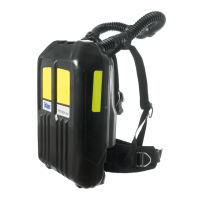
3.2 Putting on the apparatus
1. Fully loosen the shoulder straps and waist belt and put on the
breathing apparatus.
2. Check that the shoulder pads are not twisted and take the weight of the
system on the shoulders by pulling the shoulder straps. Do not fully
tighten at this stage.
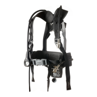
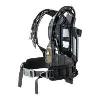
3. Close the waist belt buckle and pull the ends of the waist belt forward
until the strap padding fits securely and comfortably over the hips
(Fig D). Tuck the belt ends behind the waist pad.
4. Pull the shoulder straps until the breathing apparatus rests securely
and comfortably on the hips. Do not over tighten. Pull the strap
retainers down to secure the strap ends (Fig E).
5. Fully loosen the head straps of the face mask and place the neck strap
over the back of the neck.
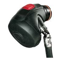
6. Press the reset button (Fig C, Item 1) to switch off the positive
pressure.
7. Open the cylinder valve (counterclockwise) slowly, but fully, to pressurize
system. The Sentinel 7000 and HUD systems will activate.
NOTICE
After storage at temperatures below 32 °F (0 °C) leakage may be observed
when the cylinder valve is initially opened due to ice formation.
● If leakage is observed from the lung demand regulator: Press the
front button (Fig C, Item 2) to allow a rush of air to pass through the
lung demand regulator and then quickly press the reset button (Fig C,
Item 1) to switch off the positive pressure. Resume normal operation.
● If leakage is observed from the quick connect cylinder coupling:
Close the cylinder valve and vent the system. Disconnect then
reconnect the cylinder to the breathing apparatus (see the Quick
Connect Cylinder Coupling instructions for use), then reopen the
cylinder valve slowly, but fully, to pressurize the system. Resume
normal operation.
● In the event that leakage still occurs, remove the breathing apparatus
from service and report the fault to trained service personnel or contact
Dräger.
WARNING
For use in a CBRN environment, use only the face mask sizes that have
been confirmed by a quantitative fit test (QNFT).
8. Put on the face mask and check for tight fit (for non-CBRN use see the
Dräger FPS
®
7000 Face Mask instructions for use; for CBRN use see the
PSS NFPA Lung Demand Regulator and CBRN Special Instructions).
3.3 During use
WARNING
Fully open all cylinder valves and ensure that they remain open during use.
Users should be in a safe area before the whistle or end-of-service time
warnings commence. Evacuate to a safe area immediately if warnings
commence during an operation.
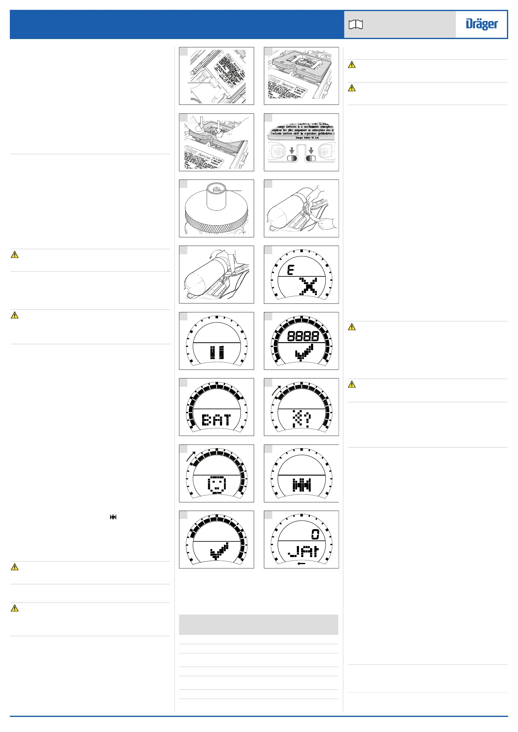
● Regularly check the user interface display to confirm the exact cylinder
pressure and the remaining time until the to end-of-service time
(EOSTI) alarm activates (see Section 8 for the EOSTI activation
pressures). Both are shown numerically on the normal operating
screen (Fig F). Cylinder pressure is also shown as follows:
○ The HUD LEDs show the approximate cylinder pressure (see
Section 3.3.1).
○ The segments on the user interface screen show the approximate
cylinder pressure (Fig F).
● To call for emergency help or assistance, press the yellow button in the
center of the user interface to activate the manual alarm.
● To illuminate the display backlight, press and release the left or right
button of the user interface.
○ Pressing the right button will also scroll any programmed personal
identity information (see Section 3.7.1).
● React to the following alarm and warning signals as necessary:
○ EOSTI – The user interface emits an audible alarm tone, and red
and blue LEDs flash and part of the display flashes red. The red
LED (R in Fig G) on the HUD flashes. The mechanical whistle on
the first-stage regulator sounds.
○ PASS pre-alarm – If no movement is detected for 21-25 seconds,
a repeating audible alarm tone is emitted from the user interface
and the second sounder. Move the user interface within
10 seconds to cancel the alarm (do not attempt to use the buttons
to switch off the pre-alarm).
○ PASS main alarm – If no movement is detected after
approximately 10 seconds of pre-alarm, a high-level sweeping
alarm is emitted from the user interface and the second sounder.
Red and blue LEDs on the user interface and the top and bottom
of the second sounder flash intermittently. The user interface
displays the automatic alarm icon ( ). To cancel the alarm,
simultaneously press and hold the left and right buttons of the user
interface until the alarm stops.
○ Low main battery – A low battery icon displays on the user interface
(Fig H), and the battery LED (G/Y in Fig G) on the HUD flashes yellow.
○ Low HUD battery – The battery LED (G/Y in Fig G) flashes green.
○ Loss of HUD communication – The blue communication LED (B in
Fig G) flashes.
WARNING
Using the bypass button (Fig C, Item 3) will use air from the cylinder and
rapidly reduce the working duration of the apparatus.
● If additional air is required, briefly press and release the bypass button
(Fig C, Item 3) to deliver a single jet of air into the face mask.
WARNING
The emergency air flow procedures below may greatly reduce the
operating duration of the air supply. When activated the user must
immediately evacuate to a safe area. The reason for using the procedure
must be investigated and repaired before reusing the apparatus.
● Additional air flow required (emergency procedure only used in the
unlikely condition of low or blocked airflow) – Press and rotate the
bypass button (Fig C, Item 3) to deliver a sustained air supply (85 to
130 liters/minute) into the face mask.
● Excessive or loss of air flow (emergency procedure only used in the
unlikely condition of high or loss of airflow) – Close the cylinder valve
then immediately begin to slowly reopen the valve. Use the cylinder
valve as a regulating valve to set the air flow to meet the user
requirement. This procedure can be used with screw-type and ratchet-
type cylinder valves.
3.3.1 Head-up display LEDs
The cylinder contents LEDs (R/A/G/G in Fig G) indicate that cylinder
pressure is within the ranges shown in the following table.
Key:
● On
*
Flashing
3.4 After Use
WARNING
Do not remove the breathing apparatus until in a safe breathing
environment.
CAUTION
Do not remove the face mask by pulling on the lung demand regulator as
this may damage the equipment.
1. Loosen the face mask straps. As the seal between the face mask and
the face is broken, press the reset button (Fig C, Item 1) to switch off
the positive pressure. Fully remove the face mask and extend all of the
straps of the head harness.
2. Close the cylinder valve.
3. Press the front button (Fig C, Item 2) to vent system and then press the
reset button (Fig C, Item 1) to switch off the positive pressure.
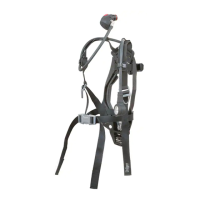
4. Release the waist belt buckle.
5. Lift the shoulder strap ends to release the strap retainers (Fig 5) and
then lift the shoulder strap buckles to loosen the straps.
6. Remove the breathing apparatus and face mask.
7. If the lung demand regulator has been set to bypass, press and rotate
the bypass button (Fig C, Item 3) to align the red spots and then
release to switch off the bypass.
8. Press and hold the left and right buttons of the user interface until the
display clears, then immediately release the buttons. After
approximately 180 seconds, all six HUD LEDs will flash twice to
indicate that the unit has logged off.
9. Carry out the after use tasks in the maintenance table (see
Section 5.1).
10. Remove the air cylinder if required (see Section 3.5.3).
11. Pass the breathing apparatus to the service department with details of
any faults or damage that occurred during use.
3.5 Common user tasks
3.5.1 Visual inspection
A visual inspection must check the full breathing apparatus including all
component parts and accessories. Check that the equipment is clean and
undamaged, paying particular attention to pneumatic components, hoses
and connectors. Typical signs of damage that may affect the operation of
the breathing apparatus include impact, abrasion, cutting, corrosion and
discoloration. Report damage to service personnel and do not use the
apparatus until faults are rectified.
3.5.2 Fitting or replacing the batteries
WARNING
Danger of explosion or fire. Do not remove or install the batteries in an
explosive or flammable atmosphere.
Explosion, fire or chemical hazard. Do not expose the batteries to heat
sources, do not attempt to recharge any non-rechargeable battery, and do
not short out the battery terminals.
Risk of explosion if battery is replaced by an incorrect type. Use only the
recommended battery type, replace batteries as a matched set, and do not
mix new and used batteries.
CAUTION
Environmental hazard. Dispose of used batteries in accordance with
national or local regulations.
NOTICE
The back-up battery will only supply power when the main battery is
disconnected or discharged. When this occurs, the back-up battery will
only supply power for HUD functions.
If the display screen switches off and the functionality of the HUD is
powered by the back-up battery during use, Dräger recommend that the
back-up battery is replaced after use.
General battery information
● The normal operating life of the batteries is dependent on operating
time, frequency of alarms and ambient temperature.
● Remove discharged batteries from the product.
System batteries:
Main battery: 7.5 V (5 x 1.5 V AA alkaline batteries)
Back-up battery: 3 V (CR123 lithium battery)
HUD battery: 3 V (CR123 lithium battery).
Use only the following approved battery types:
Procell
®
by Duracell
®
LR6 (1.5 V)
Duracell
®
Plus LR6 (1.5 V)
Panasonic
®
CR123AL/1BP (3 V).
Back-up battery
1. Orientate the apparatus to access the battery compartment.
2. Unscrew and remove the battery cap (Fig I, Item 1) using a suitable coin.
3. Insert the battery, +ve terminal end first, into the battery compartment.
4. Refit and secure the battery cap. Do not over tighten.
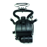
Main battery pack
1. Inspect the sealing rim around the battery terminals. Ensure that the
terminals of the battery and the pressure transmitter module are clean
and undamaged.
2. Lift and turn over the apparatus to access the pressure transmitter
module.
3. Insert the battery pack into the backplate recess (Fig J).
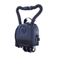
4. Position thumbs on top of the two screws and push down firmly to lock
the battery pack (Fig K).
5. Whilst pushing down, confirm the two sliding locks move to their locked
position viewed through the two keyholes as illustrated (Fig L).
6. The Sentinel 7000 will emit a single tone and will commence the self-
check sequence (see Section 3.6.1).
7. Switch off the unit if required once the unit has passed the self check.
To switch off, press and hold the left and right buttons of the user
interface until the display clears, then immediately release the buttons.
NOTICE
To remove the main battery insert and press the two pronged key (supplied
with the breathing apparatus) into the two keyholes at the base of the
battery. This will open the locking latch allowing the battery to be removed.
LEDs
Cylinder contents Red
(R)
Amber
(A)
Green
(G)
Green
(G)
100 % to 75 % ●●●●
75 % to 50 % ●●●
50% content alert (amber flashes for
20 seconds)
●
*
50 % to 35 % ●●
35 % to 100 psi (red flashes
continuously)
*
Below 100 psi HUD logs off
 Loading...