Do you have a question about the DRAKE L7 and is the answer not in the manual?
Describes the L7 amplifier's features, tube complement, and cooling system.
Outlines the manual's structure and the content of each chapter for user guidance.
Lists key technical specifications including frequency coverage, power, and dimensions.
Instructions on how to unpack the amplifier and its components, checking for damage.
Step-by-step guide for safely installing the amplifier tubes and securing the cabinet.
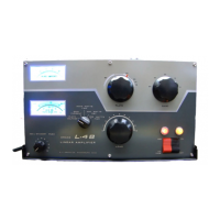
Recommendations for optimal placement of the amplifier and power supply for proper ventilation.
Details the voltage and current requirements for operating the L7 amplifier.
Diagrams and instructions for setting jumpers for 120V or 240V operation to prevent damage.
Specifies antenna impedance and SWR recommendations for optimal amplifier performance.
Recommends using a low pass filter for harmonic attenuation and compliance with FCC specifications.
Discusses the use of an antenna matching network for efficient power transfer.
Advises on proper grounding techniques for station equipment and the amplifier.
Outlines the necessary RF power output from the exciter for optimal amplifier operation.
Explains the transmitting AGC function and its connection to control exciter gain.
Describes the VOX relay connection for automatic amplifier activation during transmission.
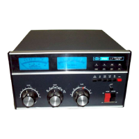
Introduces front panel controls and indicators and outlines general operating procedures.
Details the steps for tuning the amplifier for optimal performance before operation.
Specific tuning procedures for CW and RTTY modes, including control settings.
Specific tuning procedures for SSB and AM modes, including control settings and notes.
General operational notes, including plate temperature and cooling procedures.
Operating guidelines for CW and RTTY modes, focusing on power levels and tuning.
Instructions for SSB operation, including setting the transmitting AGC threshold.
Guidelines for AM operation, emphasizing controlled carrier modulation and monitoring.
Explains how to determine SWR using forward and reflected power readings and a nomograph.
Discusses operating the amplifier on non-amateur frequencies and potential retuning needs.
Describes the input pi-network and negative feedback circuit for matching and stability.
Details the function of the transmitting AGC circuit in controlling exciter gain.
Explains the circuit that cuts off plate current during standby for protection.
Describes the output pi-network used for matching the amplifier to the 50 ohm load.
Explains the operation of the directional wattmeter for measuring forward and reflected power.
Information on factory service, repair costs, and contact details for authorization.
Guidance on how to order replacement parts from the factory, including required information.
Step-by-step instructions for safely disassembling the amplifier cabinet and accessing internal components.
Procedures for cleaning dust and debris from the amplifier's interior for optimal performance.
Instructions on how to replace the amplifier tubes and potential retuning requirements.
Lists the minimum test equipment required for testing and aligning the L7 amplifier.
General advice for troubleshooting common amplifier problems and contacting factory support.
Method for testing amplifier tubes for filament-to-grid shorts using an ohmmeter.
References for locating components that require adjustment during alignment.
Detailed steps for retuning input coils when replacing tubes or operating outside amateur bands.
Instructions for zeroing and calibrating the front panel meters for accurate readings.
Overview of the wattmeter calibration process, requiring sequential steps.
Procedure for adjusting the piston trimmer C53 to minimize reflected power.
Steps to calibrate the L7 wattmeter against a standard meter for reflected power.
Steps to calibrate the L7 wattmeter against a standard meter for forward power.
Procedure to calibrate the L7 wattmeter for 3000 Watt forward power readings.
Guidance on aligning the PLATE and LOAD control knobs for proper pointer indication.
Instructions on how to reset the power supply circuit breakers if they trip.
Safety warning and instructions for removing the power supply bottom cover.
Safety warning and instructions for removing the amplifier top cover.
Troubleshooting steps for power supply failures, including circuit breaker issues and component checks.