-
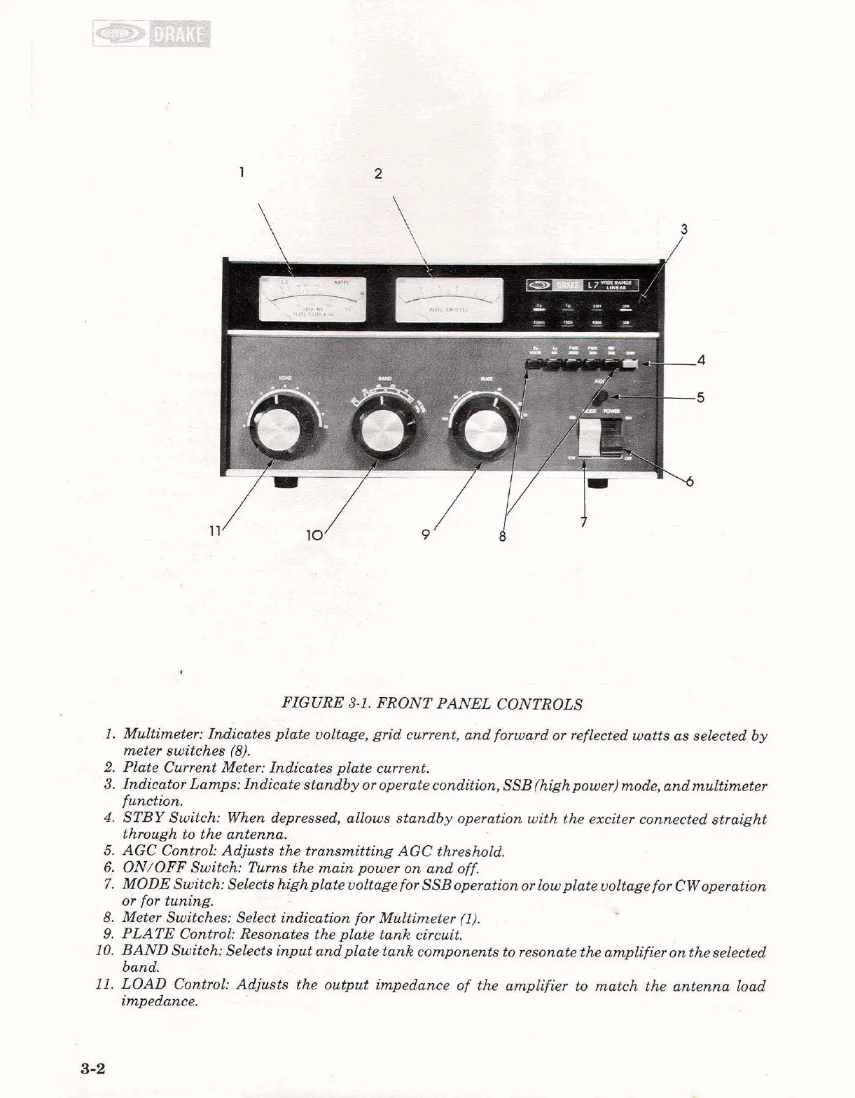
FIGURE 3-1. FRONT PANEL CONTROLS
I.
Multimeter: Indicates plate voltage, grid current, and forward or reflected watts as selected by
meter switches
(8).
2.
Plate Current Meter: Indicates plate current.
3. Indicator Lamps: Indicate standby or operate condition,
SSB (high power) mode, and multimeter
function.
4.
STBY Switch: When depressed, allows standby operation with the exciter connected straight
through to the antenna.
5.
AGC Control: Adjusts the transmitting AGC threshold.
6.
ON/OFF Switch: Turns the main power on and off.
7.
MODE Switch: Selects highplate voltage for SSBoperation or lowplate voltage for CWoperation
oi for tuning.
8.
Meter Switches: Select indication for Multimeter (1).
9.
PLATE Control: Resonates the plate tank circuit.
10.
BAND Switch: Selects input andplate tank components to resonate the amplifier on the selected
band.
11.
LOAD Control: Adjusts the output impedance of the amplifier to match the antenna load
impedance.
-%I.
:
=-.;?
.
..+
-