Do you have a question about the DRAKE MN-2000 and is the answer not in the manual?
Details frequency coverage, impedance, power, wattmeter accuracy, and insertion loss.
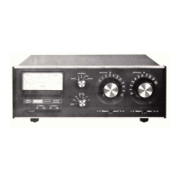
Covers unit dimensions and rear panel connector layout.
Explains the role of the matching network and lists its key capabilities.
Instructions for unpacking, locating, and connecting the MN-2000.
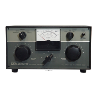
Describes the function of each front panel control on the MN-2000.
Explains bandswitch, antenna selection, meter functions, and safety precautions.
Recommended control settings and step-by-step tuning guide.
Instructions for calibrating the VSWR meter.
Methods for tuning without transmission and reading reflected power.
Guidance for using with transceivers and bypassing the network.
Guidance on using tuning curves for impedance matching.
Information on routine maintenance and troubleshooting.
Charts showing capacitor settings versus load impedance for 3.5 MHz.
Charts showing capacitor settings versus load impedance for 7.0 MHz.
Charts showing capacitor settings versus load impedance for 14.0 MHz.
Charts showing capacitor settings versus load impedance for 21.0 MHz.
Charts showing capacitor settings versus load impedance for 28.0 MHz.
Details the warranty coverage, limitations, and exclusions.
The complete electrical schematic of the MN-2000 matching network.
Important notes regarding components used in the schematic.