Do you have a question about the Draper DMM1A and is the answer not in the manual?
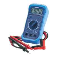
This lightweight multimeter is ideal for general electrical and automotive use.
If the fuse blows, this is usually as a result of an operator error. Open the case and replace the fuse.
If the ' sign appears on the LCD display unit, the battery needs to be replaced immediately. Replace the depleted battery.
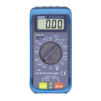
This switch is used to select the function and desired range.
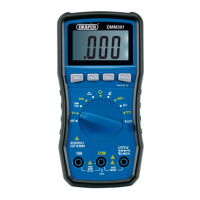
LCD display unit.
Plug in the black (negative) test lead.
Plug in the red (positive) test lead for voltage, resistance and amperage (max 200mA) measurements.
Plug in the red (positive) test lead for measuring amperage from 200mA to 10A.
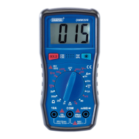
Suitable for both NPN and PNP transistors.
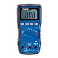
Stores reading on display.
Back Light Button.
Inspect test leads, connectors and probes for damage before use. Replace defective leads.
Connect leads, set switch to DCV range, connect to circuit, turn on power.
Connect leads, set switch to ACV range, connect to circuit, turn on power.
Connect red lead to 10A socket for >200mA, set switch to uA/mA/A range, connect in series.
Connect leads, set switch to Ohm, turn off power if in circuit, connect to circuit.
Connect leads, set switch to diode position, connect to circuit, turn on power.
Set switch to NPN/PNP hFE, insert leads into hFE socket, meter displays hFE value.
Connect leads, set switch to continuity position, connect to two points. Buzzer sounds if <100 ohms.
| DC Current Ranges | 200µA, 2mA, 20mA, 200mA, 10A |
|---|---|
| Diode Test | Yes |
| Continuity Test | Yes |
| Overload Protection | Yes |
| DC Voltage Ranges | 200mV, 2V, 20V, 200V |
| AC Voltage Ranges | 200V |
| Resistance Ranges | 200Ω, 2kΩ, 20kΩ, 200kΩ, 2MΩ |
| Battery | 9V |
| Display | 3.5 digit LCD |