Section 5 - RS232
/
RS485 Information
COMMAND COMMAND STRINGS
REMARK
UP 9A 01 01 00 0A DD D7
ID No. : 1 / Channel : 01
STOP 9A 01 01 00 0A CC C6
ID No. : 1 / Channel : 01
DOWN 9A 01 01 00 0A EE E4
ID No. : 1 / Channel : 01
For more detailed programming instructions or group control go to:
http:
//
www.draperinc.com
/
DraperPro
(registration required)
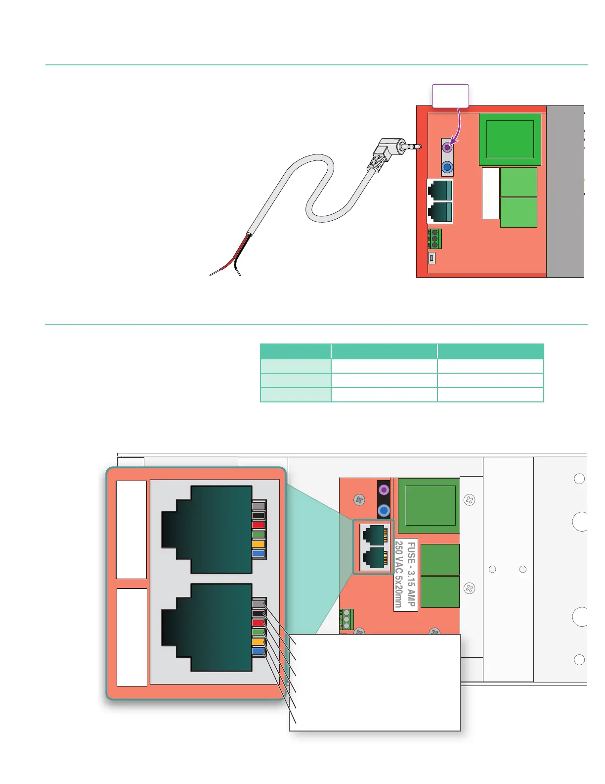
RS232 / RS485 CommPort Parameters:
1. Frequency (BAUD Rate): 2400
2. Data long code : 8
3. Parity Check : N
4. Start bit : 1
5. Stop bit : 1
6. Flow Control : NONE
FUSE - 3.15 AMP
250 VAC 5x20mm
PIN 6 - RS485-B or RS232-Rx
PIN 5 - RS485-A or RS232-GND
PIN 4 - Ground
PIN 3 - Up
PIN 2 - Down
PIN 1 - 5VDC Output
6 5 4 3 2 1
PINS
6 5 4 3 2 1
PINS
220-240V LVC-IV Low-Voltage Control Module
FUSE - 3.15 AMP
250 VAC 5x20mm
Low-Voltage wiring by others
Factory wiring
DASHED WIRING BY ELECTRICIAN
Low Voltage
Trigger
4-28 VDC
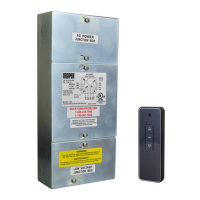
Section 4 - DC Low-voltage Trigger
The LVC-IV comes with built-in connection for sending a DC trigger (4-28 VDC) from the projector to the projection screen.
1.
Connect remote trigger voltage from projector to the low-voltage trigger cable.
2.
Plug the mini-jack plug of the low-voltage trigger cable to the LVC-IV (Figure 4).
3.
When projector is 'ON' the low-voltage output of the projector will cause LVC-IV to
deploy projection screen. When projector 'OFF' the low-voltage is removed from
LVC-IV and projection screen will retract into case.
Positive Lead
Red 24 AWG
Negative Lead
Black 24 AWG
.60" Max.
Figure 4
 Loading...