INTRODUCTION
In cases where a forced ‘service interval’ is required, a
service warning feature can be selected and programmed
by the installer only. This feature will reduce the comfort
level of the dwelling by a cycling controlled method,
The heating will run only for the first 15 mins of each hour
during the programmed time
The hot water will run only for the first 13 mins of each hour
during the programmed time.
FUNCTION
The required ‘service’ date must be set, by entering the
‘number of days’ from now to when the next service is
due and the alarm must be selected (if required)
30 days before the total ‘number of days’ have elapsed
the following warning will be shown on the display of the
programmer,
SERVICE, then...
DUE, then...
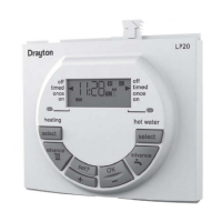
DUAL
CHANNEL
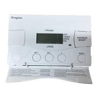
SINGLE
CHANNEL
SERVICE INTERVAL INSTRUCTIONS
For use with
for heating OR hot water
LP111Si, LP711Si
LP241Si, LP522Si, LP722Si
for heating AND hot water
FOR THE INSTALLER/SERVICE ENGINEER ONLY!
DO NOT LEAVE WITH END USER!
SINGLE
CHANNEL
Timeswitch
DUAL
CHANNEL
Programmer
SERVICE INTERVAL
Lifestyle
FUNCTION Cont...
25th DEC, then...
Todays time
The backlight will flash to draw attention!
This sequence will cycle continuously for 30 days until the preset
‘service date’ (‘number of days’) is reached.
When the ‘service date’ (‘number of days’) is reached the
display will show
SERVICE
Both the LCD and backlight will flash to draw attention!
The programmer will be functioning in the ‘reduced comfort’
mode as described earlier
All normal programmer functions will be disabled
An audible alarm will sound
The alarm can be put into ‘snooze’
for 24hrs by pressing any button
The programmer can only be returned to normal operation
by re-setting with the ‘LPSi – Reset Unit’
INSTALLER/SERVICE ENGINEER INSTRUCTIONS
Setting the Service Interval Features
NOTE: ENSURE THE TIME & DATE ARE SET CORRECTLY BEFORE
SETTING/CONFIRMING THE SERVICE INTERVAL SETTINGS
To access the menu, on the LPxxxSi unit, for the service interval
feature press the ‘-‘ (minus) button for longer than 8 (eight)
seconds and the display should show,
If the programmer is in the Service mode, i.e.SEr permanently
displayed then you will have to reset the programmer by
positioning the reset unit as shown below and pressing the
button before the service interval menu can be accessed.
Press the ‘+’ (plus) button to switch the ‘service interval’
feature on or off.
Press the SET? Button to confirm this setting. The display
should now show,
Press the ‘+’ (plus) button to switch the ‘audible alarm feature
on or off. The alarm will sound after the 30 day warning period
is complete and the service is due