“FLEX” Enclosure Rev.1, Ver.3 03/2014
6
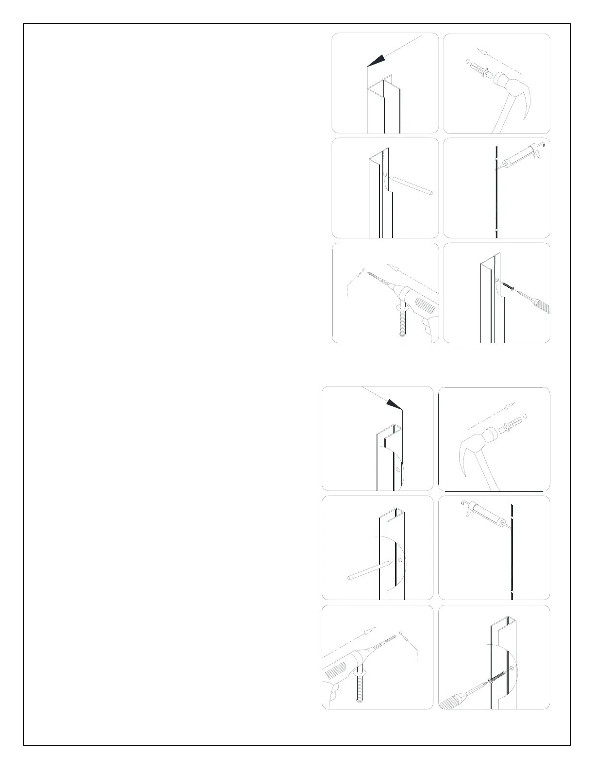
3. Trace the drilling holes on the wall through the
predrilled holes in the Wall profile (01).
Drill the holes on the wall using a Ø 5/16 drill bit
and insert the Wall anchors (03).
Apply a bead of silicone to the wall along the
drilled holes and around the holes.
Attach the Wall profile to the wall with the Round
head screws ST4.2×40 (05).
See Fig. 3 and Fig. 5 for details.
4. Trace the drilling holes on the wall through the
predrilled hole in the Return wall profile (11).
Drill the holes on the wall using a Ø 5/16 drill
bit and insert the Wall anchors (03).
Apply a bead of silicone to the wall along the
drilled holes and around the holes.
Attach the Return wall profile to the wall with
the Round head screws ST4.2×40 (05).
See Fig. 4 and Fig. 5 for details.
Fig. 4
Fig. 3
1
2
3
4
5
6
Ø 5/16"
Ø 5/16"
1
2
3
4
5
6