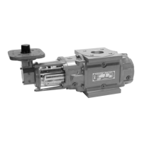
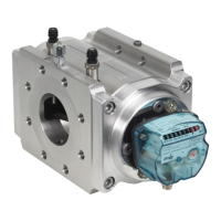
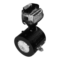
The document is an Installation, Operation & Maintenance (IOM) manual for ROOTS® Meters Series B3, specifically models 5C15 and 8C15, manufactured by Dresser Roots Meters & Instruments. The manual, identified as IOM:Z 11.06, provides comprehensive information for the proper handling, installation, operation, and maintenance of these rotary positive displacement gas meters.
Function Description
The ROOTS® Meter is a positive displacement, rotary type gas meter designed for continuously measuring and indicating the accurate measurement of gas flow in a pipeline. Its core principle involves two contra-rotating impellers, shaped like two-lobes or "figure 8s," encased within a rigid measuring cartridge. Precision machined timing gears maintain the impellers in correct relative position, ensuring optimal operating clearance without contact between impellers, cylinder, and headplates. This design effectively isolates gas at the meter inlet from the outlet, causing the impellers to rotate with a very small pressure drop. During rotation, a known volume of gas is trapped between the impeller and the cylinder wall. With one complete revolution of both impellers, the meter measures and passes four equal gas volumes. The sum of these volumes constitutes the meter's displacement per revolution, indicated in Engineering units (cubic feet or cubic meters). The volumetric accuracy of the ROOTS® Meter is permanent and nonadjustable, established by the dimensions and precision machined contours of non-wearing fixed and rotating parts.
Important Technical Specifications
- Models Covered: 5C15 and 8C15.
- Operating Temperature Range: -40°F to +140°F (-40°C to +60°C).
- Maximum Allowable Operating Pressure (MAOP): 15 psig (103kPa).
- Pressure Testing: Each meter is static pressure tested at twice its MAOP (30 psig/206 kPa) and leak tested at 125 percent of MAOP (18.75 psig/128.75 kPa) in accordance with ASME Boiler Pressure Vessel Codes.
- Pressure Range for Operation: Satisfactory for pressures ranging from a few ounces to full MAOP.
- Capacity Rating: Expressed in hundreds (C) of Actual Cubic Feet per Hour (ACFH) or in Cubic Meter per Hour (m³).
- Materials: Major components are machined or cast from aluminum for strength and weight reduction. All aluminum parts are anodized, and the measuring chamber and impellers are hard-coat anodized for added corrosion and abrasion resistance.
- Lubrication: Main bearings and timing gears are permanently lubricated; no additional oil is required.
- Index Options: Available with dial or odometer index, providing readings in ACFH (m³/h).
- Installation Configurations: Line mounted meters can be installed in Top (vertical), Side (horizontal), or Bottom Inlet (vertical) configurations. The preferred installation is a top inlet in a vertical pipe line with downward gas flow.
- Screens: A 60 Mesh screen is recommended for bottom inlet applications. A 100 Mesh screen is recommended upstream of the meter to remove liquids and foreign matter.
- Over-speed Protection: If over-speed conditions can occur, a restricting flow orifice plate should be installed 2 to 4 pipe diameters downstream of the meter outlet.
Usage Features
- Gas Compatibility: Suitable for most types of clean, dry common gases at constant or varying flow rates.
- Incompatibility: Not suitable for handling liquids, acetylene, biogas, or sewage gas.
- Accuracy: Volumetric accuracy is permanent and nonadjustable. Measurement accuracy and life expectancy can be impeded by excessive deposits of dirt or other foreign material.
- Installation Flexibility: Can be installed in various piping configurations (Top, Side, Bottom Inlet).
- Self-Cleaning Design: The impeller design inherently promotes self-cleaning, especially with top inlet mounting, allowing gravity to pass dirt and debris.
- Testing Capability: Installation of tees allows for in-line testing using a transfer prover.
- Pressure Independence: Meter accuracy is not affected by low or varying line pressures. Displaced volume measurement is independent of gas specific gravity, temperature, and pressure, and can be converted to standard conditions using Basic or Ideal Gas Laws.
- Start-Up Procedure: Requires slow pressurization (not exceeding 5 psig/second or 35 kPa/second) to prevent overspeed damage. Includes steps for verifying impeller rotation, listening for unusual sounds, and gradually opening valves.
- Troubleshooting: A checklist is provided for common issues like "No Flow Registered," "Low Volume Registration," "High Differential," and "Vibration/Noise," along with possible causes and remedies.
Maintenance Features
- Receiving and Storage: Emphasizes checking packing lists, inspecting for damage, recording visible damage, filing claims, and notifying the supplier. New meters should be checked for free impeller rotation upon arrival. If not installed immediately, meters should be stored in their original shipping container in a dry, horizontal location with protective caps installed.
- No Lubrication Required: The meter incorporates permanently lubricated bearings and gears, eliminating the need for additional lubrication.
- Meter Level: Critical for operation and accuracy. The meter must be level within 1/16” per foot (5mm/m) in any direction.
- Cleaning: If dirt or dust is present, impellers can be "windmilled" (at less than maximum capacity) by injecting controlled compressed air into the meter inlet.
- Differential Pressure Test: An accurate and convenient method to compare a meter's current performance to its original records. A change in internal resistance increases differential pressure, indicating meter condition.
- Base Line Curves: Recommended to establish an original differential or baseline curve at installation, using at least three test points (25% to 100% of meter capacity) at constant pressure.
- Test Procedure: Involves using a ROOTS® Smart manometer or similar equipment to measure differential pressure across the meter at various flow rates. A stop watch is used to "clock" meter RPM for flow rate calculation.
- Acceptance Criteria: An increase of up to 50 percent in differential pressure can be tolerated without significantly affecting accuracy at higher flow rates (25% and above). If differential pressure is higher than recommended, the meter should be inspected and serviced.
- Proving Operations: Conventional scanning methods can be used with the index for meter proving. The "Half Foot" test hand (representing 1/2 cubic foot per revolution) is the preferred focus for photocells or scanners.
- Warranty: A one-year warranty covers defects in material or workmanship, with an extended warranty for ROOTS® Rotary Positive Displacement Gas Meters used for permanent gas volume measurement. The warranty explicitly disclaims other expressed or implied warranties and limits liability for damages. Repairs or alterations without written consent void the warranty.

 Need help?
 General


 To Next Page