Do you have a question about the Dressler D 200 S and is the answer not in the manual?
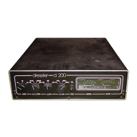
Details the TUNE, FUNCTION, LOAD, METER, and other controls on the front panel.
Provides a visual overview of the amplifier's internal components and their placement.
Explains the function of each control on the front panel, including TUNE, LOAD, METER, and FUNCTION switches.
Describes the twin meter and LED indicators that show operational status like READY, TRANSMIT, and OVERLOAD.
Details the mains socket, PTT/Us sockets, RF IN/OUT, and attenuator trimmer on the rear panel.
Explains how the SSB/FM switch affects valve bias and transmission modes for optimal performance.
Details the HI-LO switch for managing input drive power and its impact on output levels and linearity.
Lists essential pre-operation checks including power supply, antenna cable, and cooling requirements.
Describes the steps to power on, wait for the READY indicator, and change the FUNCTION switch to OPERATE.
Details how to use the METER and LOAD controls to achieve maximum output power and minimum anode current.
Covers adjusting drive power, repeating tuning steps, and handling frequency changes for optimal performance.
Explains how to use the FUNCTION control to bypass the PA for direct transmission from the transceiver.
Describes how to use the internal supply and switching for preamplifiers via the coaxial cable.
Details the function of the SSB/FM switch for mode selection and linearity in different transmission types.
Explains the HI/LO input attenuator switch and its effect on drive power levels and maximum output.
Discusses common signal quality problems like "broad" signals and splatter, attributing them to receiver overload.
Provides a table showing reasonable and maximum output power levels for different models and valves.
Identifies the three fuses in the amplifier, their ratings, and the importance of using exact replacements.
Details the steps to remove the top cover, resonator box, and carefully extract the EIMAC valve.
Explains the critical one-hour burn-in process for a new valve, including fuse removal and reinstallation.
Shows a labeled diagram of the amplifier's internal components, including fuses, valves, and modules.
Presents the schematic for the DC power supply, control logic, and associated components.
Lists the specific types and values of resistors and capacitors used in the DC section.
Details the diodes, voltage regulators, and transistors required for the DC circuitry.
Lists integrated circuits, trimmer potentiometers, RF chokes, relays, and fuses for the DC section.
Provides the specific RF circuit diagram for the Dressler D70 model.
Lists the valves, resistors, and capacitors used in the RF section for D200 and D200S models.
Shows the circuit diagram for the plug-in module and its pin connections.
Outlines the warranty period, conditions, and procedures for service or repair.
Lists components for the module and explains the RF grounding technique for all module pins.
Provides the address, telephone number, and telex for Dressler Hochfrequenztechnik GmbH.
Illustrates the physical layout and placement of components on the D 200 S printed circuit board.