Do you have a question about the Dressler D 200 and is the answer not in the manual?
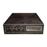
Details the main front panel controls for tuning, function, load, meter, VOX-DELAY, and SSB/FM modes.
Explains meter readings and status LED indicators for amplifier operation.
Details rear panel power input, PTT control, and US socket connections.
Describes RF connectors (IN/OUT) and the rear panel attenuator trimmer.
Explains how the SSB/FM switch affects valve bias modes.
Describes the HI/LO switch for adjusting input attenuator and drive power.
Lists essential pre-operation checks including supply voltage and cables.
Outlines the initial steps for tuning the amplifier for optimal performance.
Guides meter selection and finding maximum output power using TUNE/LOAD.
Emphasizes monitoring currents to prevent valve damage during tuning.
Explains how to transmit directly from the transceiver without using the PA.
Details connecting, powering, and switching external preamplifiers.
Warns against activating 'PREA' mode without a connected preamp.
Explains mode switch impact on valve bias modes.
Describes input attenuator for power adjustment.
Discusses causes of distorted signals and receiver overload.
Provides power output specifications for different amplifier models.
Details fuse identification, ratings, and locations for replacement.
Guides the process of safely removing and installing the vacuum valve.
Lists DC-section resistors and capacitors with values.
Lists other DC-section electronic components.
Lists integrated circuits and variable resistors for the DC section.
Lists RF chokes, relays, and fuses for the DC section.
Lists HF-section resistors and capacitors with values.
Lists HF-section RF chokes, relays, and switches.
Details module connection pins, circuit diagram, and component list.
Covers general terms and conditions of the product warranty.
Clarifies that EIMAC valves are not covered by the Dressler warranty.
Outlines specific warranty conditions, duration, and claims process.
| Model | D 200 |
|---|---|
| Category | Amplifier |
| Input Impedance | 47 kOhms |
| Weight | 12 kg |
| Power Output | 200W |
| Frequency Response | 20 Hz - 20 kHz |
| Total Harmonic Distortion | <0.05% |
| Input Sensitivity | 1V |
| Dimensions | 430 x 150 x 400 mm |