EasyManua.ls Logo

Dressler D 70 - User Manual

Default Icon
25 pages
Print Icon
To Next Page IconTo Next Page
Loading...
Question and Answer IconNeed help?

Do you have a question about the Dressler D 70 and is the answer not in the manual?

Summary

Amplifier Visual Identification

Front Panel Overview

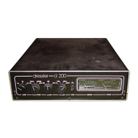
Visual layout of the front panel controls and indicators.

Internal and Rear Panel View

Examination of the amplifier's internal structure and rear panel connections.

Equipment Description and Controls

Detailed Control Element Explanations

In-depth description of each front panel control and its function.

Model D 200 S Specific Features

FM;SSB Mode Selection Functionality

How the FM/SSB switch affects valve bias and transmission modes.

Input Attenuator (HI;LO) Control Usage

Explanation of the HI-LO switch for managing input drive power.

Operation Preparation and Initial Tuning

Essential Pre-Operation Preparations

Checklist of critical steps before operating the power amplifier.

Initial Power Amplifier Tuning Steps

The first sequence of actions for tuning the amplifier.

Tuning Optimization and Drive Power Management

Optimizing Output Power and Load Matching

Procedure for achieving maximum output power via TUNE and LOAD.

Tuning for Drive Power and Frequency Changes

Re-tuning considerations for frequency or drive power changes.

Special Operation Modes

Stand-by Mode for Transmission Bypass

Utilizing stand-by to transmit directly from the transceiver.

Preamplifier Connection and Operation

Guidelines for integrating and operating with preamplifiers.

D 200 S Additional Features Explanation

Detailed D 200 S Feature Explanations

Further explanation of the SSB/FM and HI/LO controls.

Performance Issues and Power Levels

PA Output Disturbance Factors

Analysis of signal quality issues and causes of distortion.

Comparative Power Output Levels

Chart comparing reasonable and maximum output for different models.

Component Replacement: Fuses and Valves

Fuse Types and Replacement Procedure

Identification and steps for replacing amplifier fuses.

EIMAC Valve Replacement Guide

Step-by-step instructions for safely replacing the EIMAC valve.

New Valve Burn-in Procedure

New Valve Pre-Operation Burn-in Steps

Critical procedure for heating and preparing a new valve.

Internal Component Diagrams

Labeled Internal Component View Diagram

A detailed diagram identifying key internal components.

Technical Circuit Schematics

DC Section Circuit Diagram

Schematic diagram illustrating the DC power and control circuitry.

Component Lists

DC Section Parts List

Inventory of components used in the DC section of the amplifier.

HF System D70 Circuit Diagram

HF System D70 Schematic

Schematic diagram specific to the HF system of the D70 model.

RF Stage Component List

RF Stage Parts List

Inventory of components used in the RF section of the amplifier.

Module Connectivity and Parts

Module Circuit Diagram and Parts List

Details on module connections and its constituent parts.

Printed Circuit Board Layouts

D 200 S PC Board Component Placement

Diagram showing the layout of components on the D 200 S PCB.

Warranty and Manufacturer Information

Warranty Regulations and Return Policy

Terms and conditions governing the product warranty.

Dressler D 70 Specifications

General IconGeneral
BrandDressler
ModelD 70
CategoryAmplifier
LanguageEnglish

Related product manuals