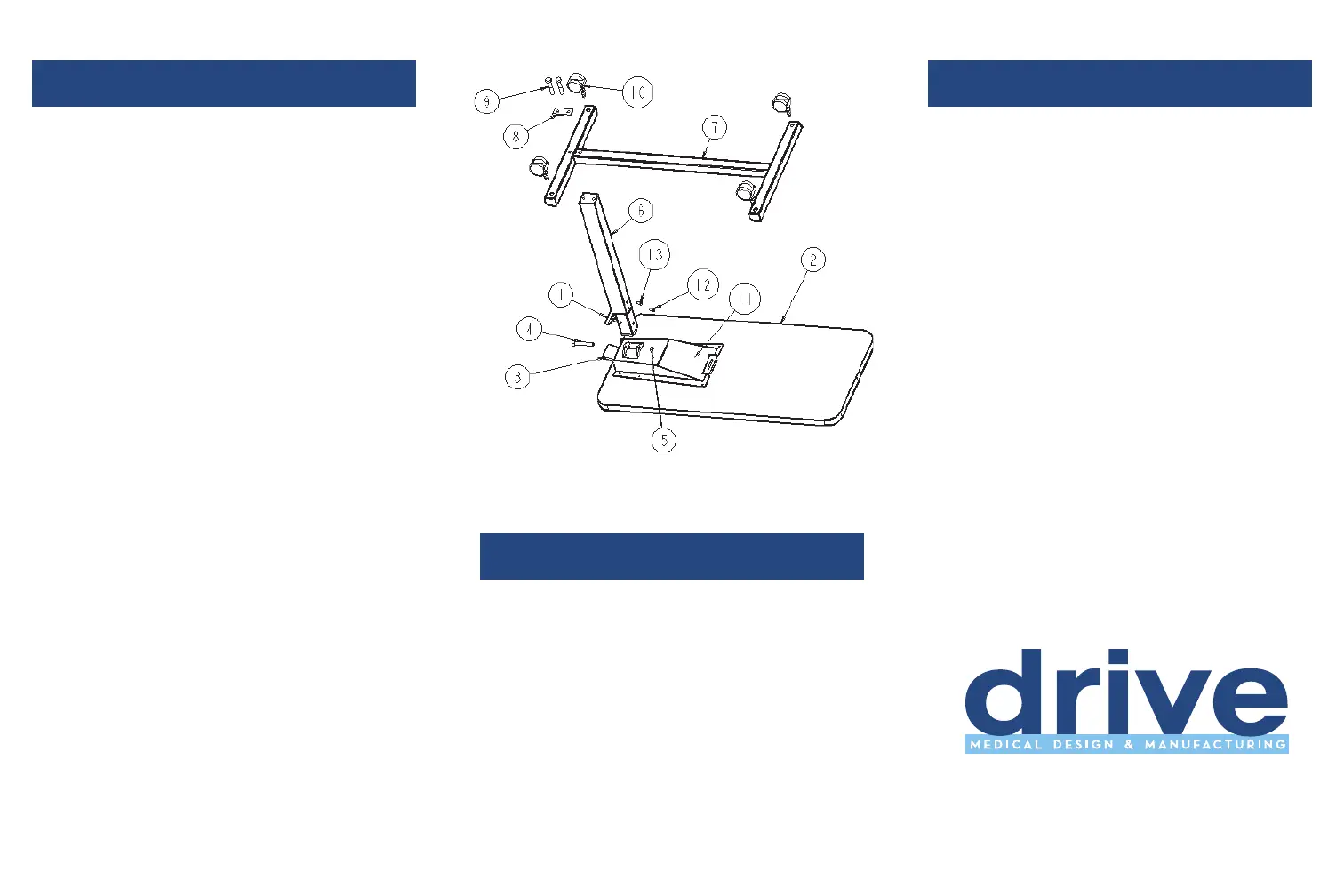
assembly instructions
1 Lay tabletop Assembly (#2 ) on flat
surface with top bracket assembly facing up,
as shown in Fig. 1.
2 Install column assembly into top bracket as
shown with release handle facing away from
table top edge (fig. 1). Insert shoulder bolt
(#4) through top bracket and column
assemblies. Fasten with locknut (#5)
3 Lay the base flat with holes facing up and
insert a caster (#10) into each hole.
(4 casters total)
4 Place the two bolts (#9) into the bolt plate
(#8) and place through the base (#7). Hold
base steady while hand tightening bolts (#9)
into column (#6).
5 Align the base and top assembly by laying the
table on its side, resting on the edge of the
top and the black caster plugs. Tighten the
bolts (#9) with a 9/16” wrench.
6 Stand the table up on its casters.
7 Remove black lock screw in the column and
discard. Replace with the extra zinc
plated screw shipped with unit, using a
Phillips screwdriver.
fig. 1
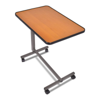
operating instructions
1 Pull the release handle (#1) up to raise and
lower the tabletop.
2 To tilt the tabletop in either direction, squeeze
the tilt lock lever (#3) up and rotate the
tabletop. Release Tilt Lever to lock the top
into place.
parts list
1. Release Handle (101044)
2. 15 x 30 Table Top
3. Tilt Lock Lever (093025)
4. Shoulder Bolt (093011)
5. 3/8-16 Lock Nut (N06)
6. Column Assembly (95001)
7. Base with Caster Plugs
8. Bolt Plate (101023)
9. 3/8 –16 x 2 bolts (BT01)
10. Casters (CA02)
11. Top Bracket (093008)
12. Black Shipping Screw
13 Zinc Screw (do not remove)
tools required
Phillips Screwdriver
(2) 7/16” Wrenches
9/16” Wrench