9
METRO 100 INSTALLATION MANUAL
English
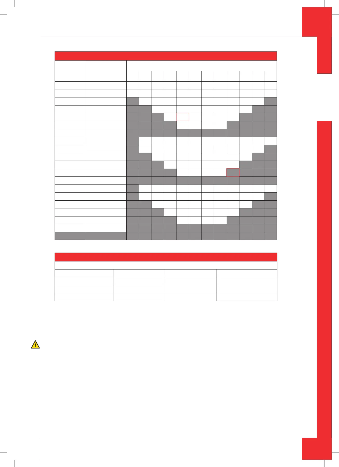
Table 2: Determination of th e permissibility of a concentric system with a roof terminal
G20 / G25 Total number of
meters horizontal
pipe length
Total number of meters vertical and/or sloping pipe length
1234
↓5
678
↓9
10 11 12
no bends 0 B B B B B B B C C C C C
2 bends 0 A A B B B B B B B C C C
1 AABBBBBBBC
2 AABBBBBB
→
3AABBBB
4AABB
5
3 bends 0 A A B B B B B B B C C
1 AAABBBBBBB
2 AAABBBBB
3AAABBB
→
4AAAB
5
4 bends 0 A A A B B B B B B B C
1 AAAABBBBBB
2AAAABBBB
3AAAABB
4AAAA
5
5 bochten -
■ = situation is not allowed
Table 3: Condi tions for the adjustment of the appliance with a roof terminal
G20 / G25
Situation Air inlet guides Ba e Distance of restriction in mm
A NO NO OPEN
B YES YES 51
C YES YES 33
6.5.3.2 Placing concentric system with roof terminal
The roof terminal can end in a sloping and a at roof.
The roof terminal can be supplied with an adhesive plate for a at roof or with a universally adjustable tile for a
sloping roof.
Caution
- Maintain a distance of at least 50mm between the outside of the concentric system and the walls and/or the ceiling.
If the system is built in (for instance) a cove, it should be made with non combustible material all around it;
- Use heat-resistant insulation material when passing through combustible material.
!Caution
Some heat-resistant insulation materials contain volatile components that will spread an unpleasant smell for a pro-
longed time; these are not suitable.
Place the concentric system as follows:
➠
Build the system up from (the connection stump of) the appliance.
➠
Connect the concentric pipe pieces and, if necessary, the bends.
➠
On each connection, apply a clip binding with silicon sealing ring.
➠
Use a self-tapping screw to x the clip binding to the pipe on locations that cannot be reached after installation.
GB
95900005_ML1 Install.indd 995900005_ML1 Install.indd 9 4-3-09 8:074-3-09 8:07



 To Next Page