3
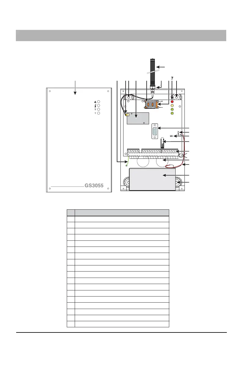
IDENTIFICATION OF PARTS
The numbers in square brackets
[[
[[
[
]]
]]
] in this manual refer to the main parts of the GS3055-I (see Fig.1
below) described in this section.
1
51
96
LE LI
-
O1
M
O2 O3 O4
+OC
AS
M
L1 L2 L3 L4 +12V-
LOCK
OPEN
44
5
18
3
2
6
17
10
11
8
12
14
13
16
15
4
9
-I
12 13
TAMPER
9
PGM3
8
PGM2
19 20
+ 12V -
11
AUX+
16
Z2
17
Z3
15
Z1
14
COM
10
PGM4
7
PGM1
6
COM
4
T1
5
R1
2
TIP
3
RNG
1
18
Z4
JP3
tie wrap
All circuits are classified for UL installations as Power Limited/Class II Power Limited except for the bat-
tery leads which are not power limited. Do not route any wiring over circuit boards. Maintain at least 1”
(25.4mm) separation. A minimum 1/4” (6.4mm) separation must be maintained at all points between
Power Limited wiring and all other Non-Power Limited wiring. Route wires as indicated in the diagram.
N
PA R T S
1
2
3
4
5
6
7
8
9
10
11
12
13
14
15
16
17
18
Metal Casing
GSM Antenna
GSM Antenna Nuts
Anchor Screw Holes (3mm)
Connector for GSM Antenna
SIM Card
LEDs
JP3 Current Limitation Jumper (refer to ratings section)
Reserved Jumper
RS-232 Connector
Front plate Tamper Switch
Terminal Blocks
Battery Connector
Cable Entry
Earth Ground Wire
12V-1.2Ah Battery
GSM Module
SIM Holder
Figure 1 - Parts
 Loading...