Installation Instructions
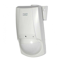
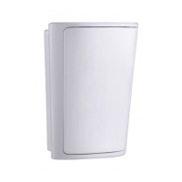
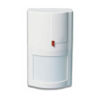
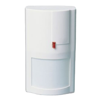
LC-101CAM Series Mono/Colour
Quad Element PIR Mono/Colour Camera
Motion Detector with Pet Immunity
Video sensing device * High sensitivity and high resolution board camera. * Electronic shutter control.
Audio sensing device * Omnidirectional response.* High sensitivity.
FIG 1 - Knockout holes
FIG 3 - Lens pattern
TYPICAL INSTALLATION
Select mounting location
Choose a location most likely to intercept an intruder. (Our recommendation is a corner installation). See detection pattern (Fig.3). The quad-
element high quality sensor detects motion crossing the beam; it is slightly less sensitive detecting motion toward the detector. The LC-101CAM
performs best when provided with a constant and stable environment.
Avoid the Following Locations * Facing direct sunlight. * Facing areas that may change temperature rapidly. * Areas where there are air ducts
o r substa ntia l ai rflo ws. Th e LC-10 1CA M perfo rm s b etter wh en provi ded w ith a co nstant a nd stabl e en vi ronm ent.
MOUNTING DETECTOR BASE
1. To remove the front cover, unscrew the holding screw and gently raise the front cover. Fig.2-12 2. To remove the PC board, carefully unscrew
the holding screw located on the PC board. Fig.2-7 3. Put wire through the bracket and holes “A”. Fig.1 4. Mount the detector base to the wall
or on the ceiling with a suitable bracket. (Install bracket). 5. Reinstall the PC board by fully tightening the holding screw. Connect wire to terminal
block. Fig.5 6. Connect the camera cable to connector in PC 7. Replace the cover by inserting it back in the appropriate closing pins and screw
in the holding screw.
DETECTOR INSTALLATION
Terminal Block Connections (See Fig.5)
Terminals 1 & 2 - Marked “T1,T2” (TAMPER) If a Tamper function is required connect these terminals to a 24-hour normally closed protective
zone in the control unit. If the front cover of the detector is opened, an immediate alarm signal will be sent to the control unit.
Terminals 3 & 4 - Marked “AUDIO: OUT, GND” This is the audio signal output. These two terminals should be connected to an audio input.
Terminals 4 & 5 - Marked “VIDEO: GND, OUT” This is the video signal output. These two terminals should be connected to video input.
Terminals 6,7 & 8 - Marked “RELAY: NO, COM & NC” These are the output relay contacts of the detector. Connect to a normally closed or
normally opened zone in the control panel.
Terminal 9 - Marked “-” (GND) Connect to the negative Voltage output or ground of the control panel.
Terminal 10 - Marked “+ “(+12V) Connect to a positive Voltage output of 8.2 -16Vdc source (usually from the alarm control unit)
FIG 2 - Detector Installation
FIG 4 - Terminal block
15m
B
A A
1 3 7
5 4
6
12
7
10
8
9
11
AUDIO VIDEO RELAY
1 2 3 4 5 6 7 8 9
OUT - 12V +T1 GNDT2 C NCN.OOUT
10
A new generation of professional movement spread analyzing PIR detectors with Mono / Colour Camera