1
About Your Security System
Your DSC Power832 Se curity System has been desi gne d to provi d e you with the gre atest possible
fl exi bility and convenienc e. Read this manual carefully and have your install er instruct you on your
system's op eration and on which fe atures have been impl emented in your system. All users of this
system should be equally instructed in its use. Fill out the “ System Information” pag e with all of you
zone information and access cod es and store this manual in a safe pla c e for future referenc e.
Fire Detection
This equi pment is ca p a ble of monitoring fire dete ction devic es such as smoke d etectors and provi ding
a warning if a fire condition is dete cted. G ood fire dete ction depends on having a de quate number of
dete ctors pl a ce d in a p propriate locations. This equi pment shoul d be installe d in accord ance with
NFPA 72 (N. F.P.A., Batterymarch Park, Q uincey MA 02269). C arefully revi ew the F amily Esca p e
Planning gui d elines in this manual.
NOTE: Your installer must enable the fire detection portion of this equipment before it becomes
functional.
Testing
To insure that your system continues to function as intend e d, you must test your system weekly.
Please refer to “ Testing Your System” on page 13 of this manual. If your system does not function
properly, c all your installing comp any for servi c e.
Monitoring
This system is capa bl e of transmitting alarms, troubl es and emerg ency information over tel e phone
lines to a monitoring station. If you inadvertently initi ate an al arm, immedi ately call the monitoring
station to prevent an unnecessary response.
NOTE: The monitoring function must be enabled by the installer before it becomes functional.
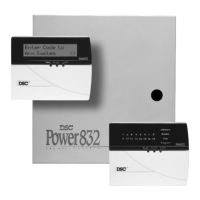
General System Operation
Your security system is ma de up of a DS C Power832 control panel, one or more Power832 keyp a ds
and various sensors and dete ctors. The control p anel will be mounte d out of the way in a utility closet
or in a basement. The metal c a binet contains the system ele ctroni cs, fuses and stand-by battery.
There is normally no re ason for anyone but the installer or servic e professional to have a c c ess to the
control p anel.
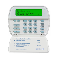
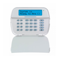
All the keyp a ds have an audi bl e indi cator and command entry keys. The LED keyp ads have a group
of zone and system status li ghts. The L C D keyp a d has an alphanumeric li qui d crystal displ ay (L C D).
The keyp a d is use d to send commands to the system and to displ ay the current system status. The
keyp a d(s) will b e mounte d in a convenient location insid e the prote cted premises close to the entry/
exit door(s).
The security system has several zones of are a protection and e a ch of these zones will b e connecte d
to one or more sensors (motion detectors, gl assbre ak dete ctors, door contacts, etc.). A sensor in
alarm will be indi c ate d by the corresponding zone lights fl ashing on a LED keypad or by written
messa ges on the L C D keyp a d.
IMPORTANT NOTICE
A security system cannot prevent emergencies. It is only intended to alert you and – if included –
your monitoring station of an emergency situation. Security systems are generally very reliable
but they may not work under all conditions and they are not a substitute for prudent security
practices or life and property insurance. Your security system should be installed and serviced by
qualified security professionals who should instruct you on the level of protection that has been
provided and on system operations.