Do you have a question about the DTI HV-500 Series and is the answer not in the manual?
Records changes and versions of the user manual.
Lists other relevant manuals for the HV-500 system.
Outlines critical safety precautions and user responsibilities for operating the inverter.
Details the inverter's internal discharge resistors and time after power off.
Explains the meaning and importance of various warning signs on the inverter.
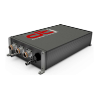
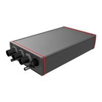
Lists the primary features and capabilities of the HV-500 inverter.
Differentiates HV-500 models based on cooling and upgrade options.
Describes the information found on the HV-500 inverter's nameplate.
Provides detailed DC electrical specifications for the HV-500 inverter.
Provides detailed AC electrical specifications for the HV-500 inverter.
Details physical dimensions, weight, and thermal operating limits.
Lists the technical parameters for the HV-500ACx air cooling fans.
Details the pin assignment and wire gauge for the cooling fans.
Covers liquid cooling connection details like tube size and coolant.
Presents a graph showing the relationship between thermal resistance and water flow.
Tabulated data on power losses under various DC voltage and AC current conditions.
Visualizes power dissipation as a function of AC current at different DC voltages.
Discusses key factors influencing the system's overall efficiency.
Displays a graph illustrating system efficiency at different power and speed levels.
Provides detailed mechanical drawings for the HV-500LCx endplates.
Shows top and side mechanical views with critical dimensions for the HV-500LCx.
Details supported encoder types, signals, and resolution.
Specifies compatible resolver types and the need for a DTI Resolver Interface.
Lists Hall-effect sensor types and their input signal specifications.
Outlines the parameters needed to configure compatible PMSM motors.
Pinout details for the HV-500 harness connector on the inverter.
Describes the pin assignment for the motor sensor connector.
Illustrates the wiring connections for HALL sensors.
Lists compatible high-power connector receptacles and their specifications.
Explains the procedure and importance of proper chassis grounding.
Details the DTI Tool for inverter parameterization and PC control.
Refers to a separate manual for firmware update instructions.
General overview of controller wiring, safety, and precautions.
Specifies connector types, crimp pins, and tools for harness assembly.
Explains CAN bus wiring for firmware updates and diagnostic tool use.
Schematic diagram for the power supply input with protection circuits.
Schematic diagram for analog signal inputs, including filtering and protection.
Schematic diagram for digital signal inputs, showing debounce and protection.
Schematic diagram for digital signal outputs, detailing current and protection.
Schematic diagram for CAN peripheral interface with ESD protection.
Schematic diagram for RS 232 peripheral interface with ESD protection.
Illustrates a basic functional schematic of the HV-500 system.