DO ALL RUNTIME (Calibrating) AND TRANSMITTER PROGRAMMING BEFORE CONNECTING ANY
ADDITIONAL INPUTS SUCH AS, –INTERCOM, EXTERNAL RECEIVERS, BEAMS, ETC.
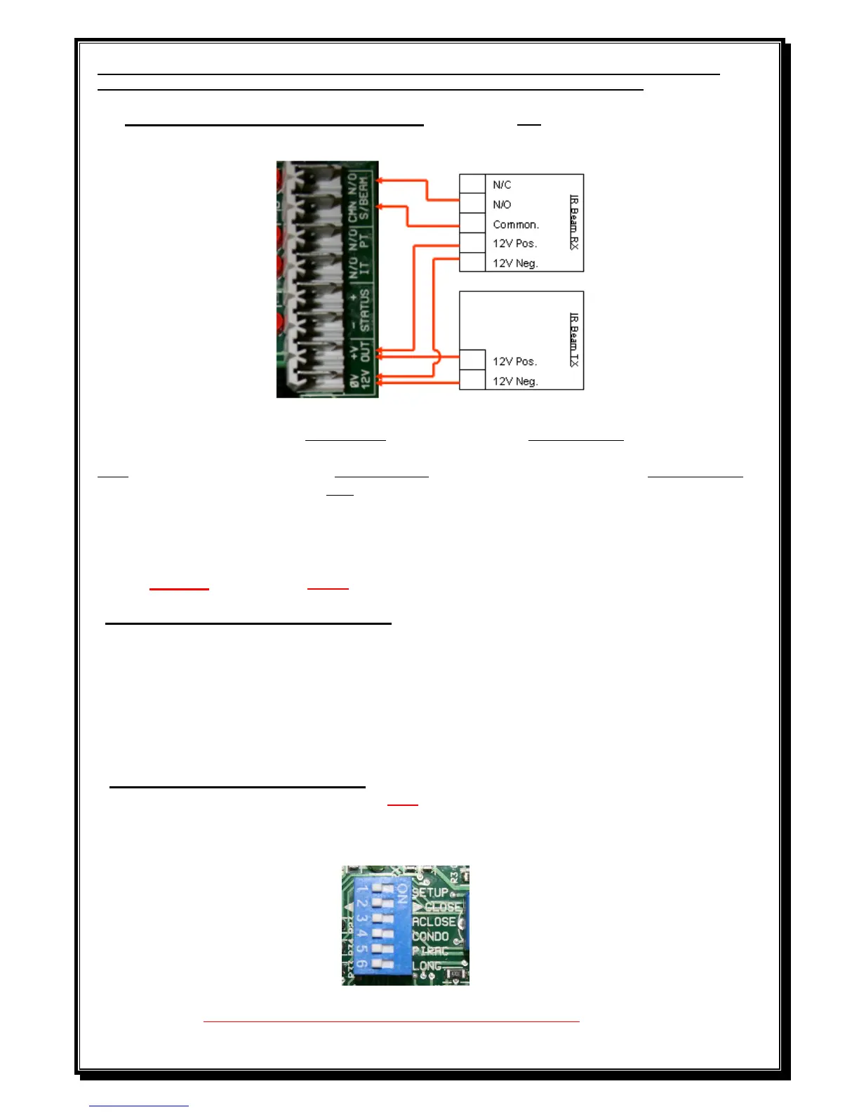
Diagram to connect IR Beams to PCB (Beam pins not bridged, The pins are next
to the BT/SET button)
With the beam pins bridged, the S/Beam N/O must be connected to N/C on the RX (Receiver)
Note: If sentry beams are fitted, then S/BEAM, N/O on the PCB must be connected to N/C on the RX
with the pins not bridged and N/O if the pins are bridged.
(Please note that the 12V OUT on the 512 PCB’s is an unregulated voltage up to 22Volt DC on PCB’s
up to S/N 01622836).
(PCB’s from S/N 01622837 onwards, the 12V OUT will be regulated to 12Volt DC for 512 & 624).
NOTE- IR beams must be fitted if a DTS624 motor is installed.
Dipswitch selections to activate a function.
Dipswitch 1 – Programming.
2 – Motor direction. (This can only be changed before programming or if neither limit
switches are activated).
3 – Auto close.
4 – Condominium mode.
5 – P.I.R.A.C. mode
6 – Slow down distance change
Dipswitch selection for programming. (With dipswitch 1 ON)
Dipswitch 3 – Auto close. (Infra red beams must be fitted if auto close is activated).
Dipswitch 4 – Pedestrian (Open distance and auto close time).
DO NOT CONNECT 220V DIRECTLY TO PCB