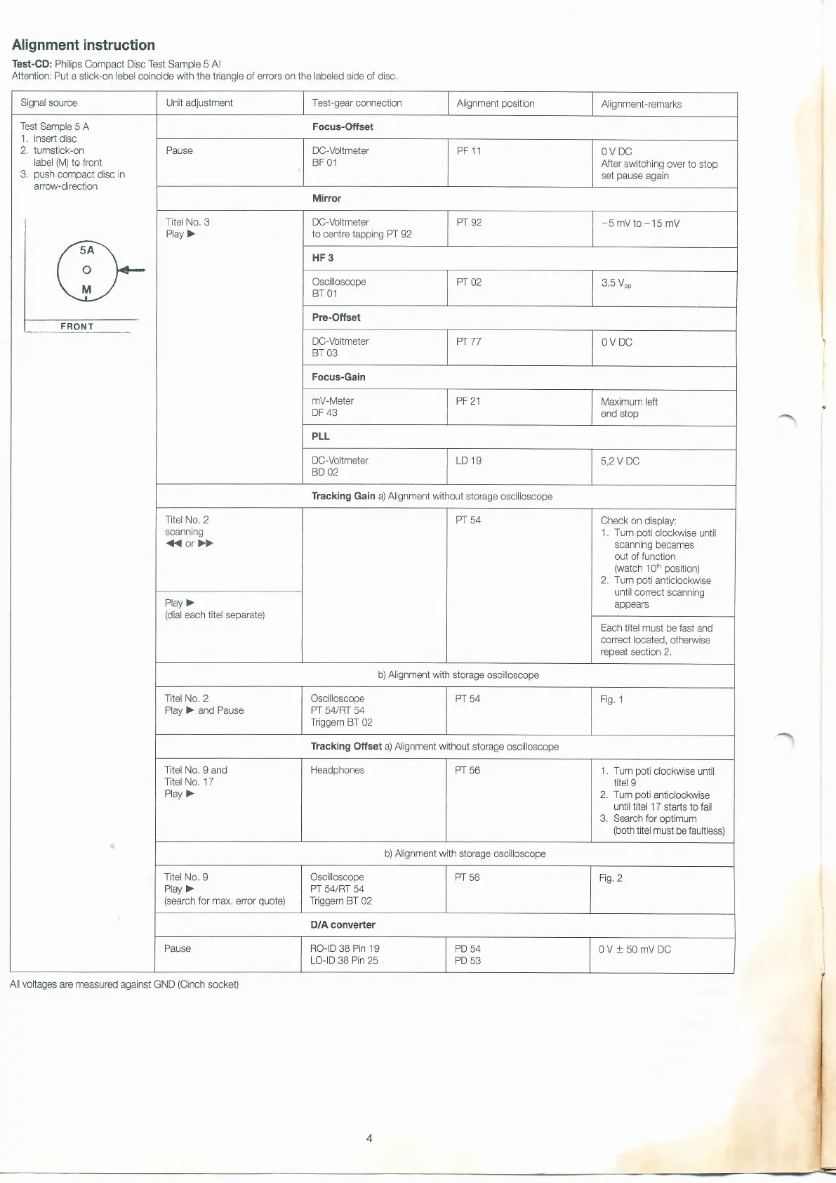
Alignment instruction
Test-CD:
Philips
Compact
Disc Test
Sample
5 Al
Attention: Put
a stick-on lebel coincide
with the triangle
of errors on
the labeled
side of disc.
Signal source Unit adjustment Test-gear connection
Alignment
position
Alignment-remarks
Test Sample
5
A
1, insert
disc
2.
turnstick-on
label
(M)
to front
3,
push
compact
disc
in
arrow-direction
Focus-Offset
Pause
DC-Voltmeter
BF 01
PF 11
OV DC
After
switching
over
to
stop
set
pause
again
Mirror
Titel No.
3
Play >
DC-Voltmeter
to centre tapping PT 92
Pr
92
-5mVto-15mV
HF3
Oscilloscope
BT 01
PT
02
3,5
Vpp
Pre-Offset
DC-Voltmeter
BT 03
Pr
77
OV DC
Focus-Gain
mV-Meter
DF
43
PF 21
Maximum left
end stop
PLL
DC-Vollmeter
BD 02
LD 19
5,2 V DC
Tracking Gain a) Alignment without
storage oscilloscope
Titel No. 2
scanning
(or})
Pr 54
Check on
display:
1, Tum
poti
clockwise
until
scanning becames
out of function
(watch
1Oth
position)
2, Tum
poli
anticlockwise
until correct scanning
appears
Play >
(dial
each
titel
separate)
Each titel
must be fast
and
correct located,
othenrvise
repeat section
2,
b)
Alignment
with storage oscilloscope
Titel No. 2
Play ) and Pause
Oscilloscope
Pr 54/Rr 54
Triggern BT
02
PT 54
Fig.
1
Tracking Offset a) Alignment without
storage oscilloscope
Titel No. I
and
Titel No. 17
Play
)
Headphones
PT 56
1. Tum
poti
clockwise until
titel
9
2. Turn
poti
anticlockwise
until titel 1 7 starts to
fail
3. Search for
optimum
(both
titel
must be faultless)
b)
Alignment
with storage
oscilloscope
Titel No. I
Play >
(search
for max.
error
quote)
Oscilloscope
Pr 54/Rr 54
Triggern BT
02
PT 56
Fig.2
D/A converter
Pause
RO-ID
38
Pin 19
LO-ID
38
Pin
25
PD
54
PD
53
0V+50mVDC
All voltages
are measured against GND
(Cinch
socket)
 Loading...